Key Takeaways
- Dairy beverage plant layout, land, building and utilities must be planned together with capacity, product mix, machinery and hygiene zoning – not as an isolated civil-construction decision.
- Layout choices directly affect project cost, operating efficiency, food safety, working capital, utilities consumption and long-term bankability of the dairy beverage project.
- There is no universal square-foot-per-litre thumb rule; land and building needs depend on product range, packaging format, automation level, storage days and future expansion strategy.
- Utilities such as power, steam, chilled water, refrigeration, compressed air, water and the effluent treatment plant, along with CIP systems, must be integrated into the layout from day one to avoid costly rework and hidden operating losses.
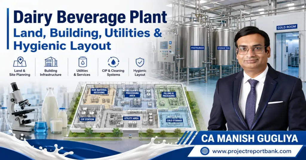
- This article is written by CA Manish Gugliya for Indian entrepreneurs and lenders, focusing on practical project-planning, DPR preparation and financial-feasibility implications.
Importance of Proper Infrastructure Planning in a Dairy Beverage Plant
A dairy beverage plant layout should never be frozen before capacity, SKU mix, packaging and process route are broadly finalised. Too many promoters treat civil works as a starting point. In reality, the facility layout should be developed from the process flow outward – letting the building follow the process, not the other way around.
Consider how production capacity interacts with product configuration. A 20,000 LPD plant producing 200 ml PET bottles of flavoured milk will have vastly different space, refrigeration and utility requirements compared to a 1,00,000 LPD plant filling 1-litre aseptic cartons of UHT dairy beverages. Designing an efficient layout for a dairy beverage processing plant requires balancing hygiene standards and workflow optimization across every functional block. Dairy products are highly perishable and sensitive to contamination, which makes every layout decision directly relevant to food safety and product quality.
A chilled milkshake line needs robust cold rooms and refrigerated dispatch, while a shelf-stable UHT line demands sterile air systems and aseptic fillers – same litres-per-day, completely different building and utility footprints. Automation level also matters: manual crate handling requires wider aisles and forklift clearances, while fully automatic conveyors and palletisation need taller ceilings, service corridors and more utility infrastructure. Buffer tanks in processing can prevent operational disruptions, but they need space and piping that must be planned early. Poorly planned infrastructure increases material handling distances, cleaning time, product losses and energy bills, ultimately weakening DSCR and project bankability. A strong plant design supports better hygiene zoning, traceability, CIP effectiveness and regulatory compliance.
Factors Determining Land Requirement
Land requirement for a dairy beverage manufacturing plant cannot be fixed by one benchmark. It depends on capacity, product mix, local FSI rules, storage philosophy and future expansion plans.
Core drivers include:
- Installed capacity (LPD) and number of processing and filling lines
- Extent of cold storage vs ambient warehousing
- Size of utility block, ETP footprint and water treatment plant
- Internal roads, mandatory setbacks, fire-access lanes and green areas
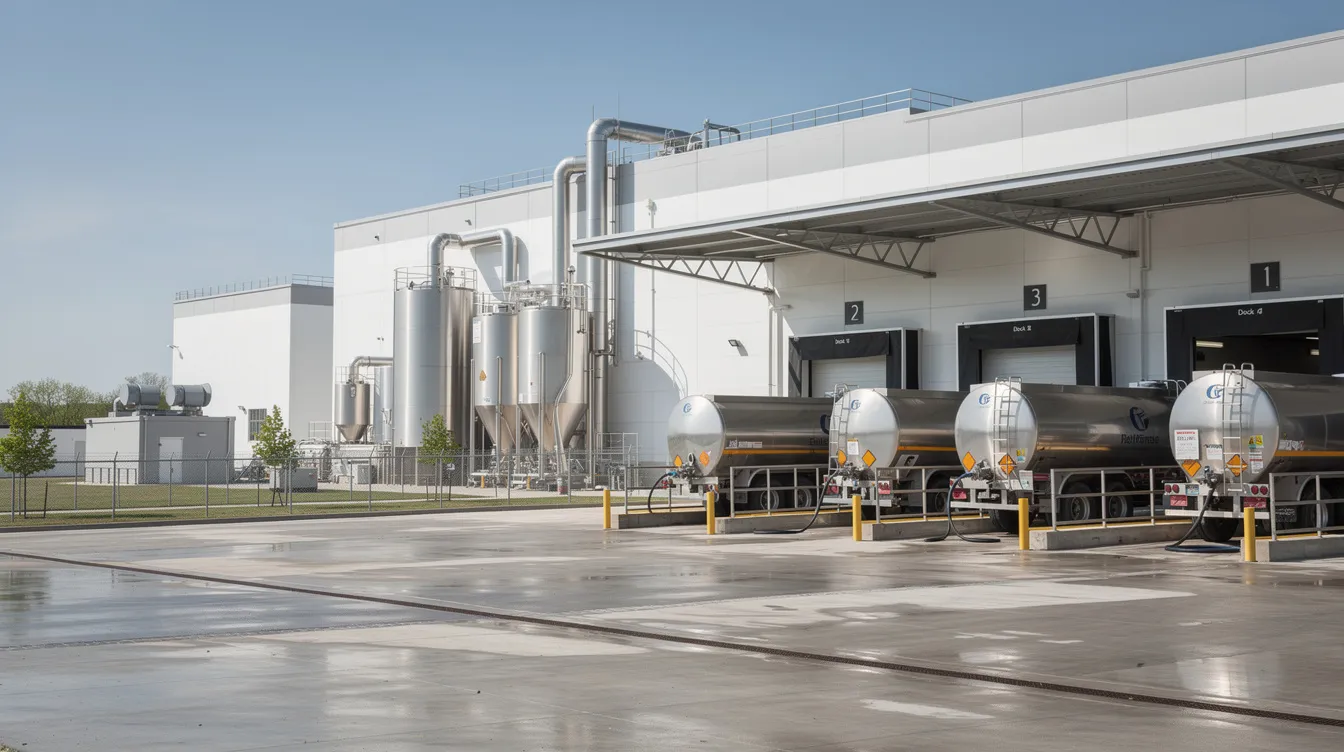
- Raw milk reception system – tanker vs can handling, approach roads, turning radius, weighbridge and parking bays
Dairy plants should accommodate peak flush volumes in design, not just average daily throughput. A dairy plant handling 10,000 liters of milk requires about 4,000 sq ft of built-up area as a rough starting point. For a 1,00,000 LPD plant producing liquid milk plus value-added products, indicative estimates suggest approximately 1.0–1.5 acres of plot area with 40,000–60,000 sq ft of built-up area. These are illustrative only and depend entirely on actual design, zoning rules and technology selection.
Promoters must distinguish between total plot area, permissible built-up area (FSI), production block area, utility and service area, warehousing and circulation or open space – all of which must be reconciled in the DPR.
Site Selection Considerations for a Dairy Beverage Manufacturing Plant
Site selection has a lasting impact on both operating cost and project feasibility. Key considerations include:
- Milk procurement proximity: Closer to milk collection centres, chilling stations or cooperative suppliers reduces transportation time and spoilage risk
- Market connectivity: Proximity to national or state highways and major consumption markets optimises logistics cost and turnaround time for finished RTD dairy beverages
- Power and water: Reliable power supply (three-phase), industrial water source and feasible wastewater disposal options; early interaction with DISCOM and the local industrial development authority is advisable
- Labour: Availability of both skilled and unskilled workers, local wage levels and social infrastructure, especially for plants operating in two or three shifts
- Zoning and environment: Industrial zoning or food-park land vs agricultural land, environmental sensitivity, flood risk and long-term expansion potential
- Future utility capacity: Site selection must consider future utility capacity for growth – a site that cannot accommodate additional transformers, boilers or chillers becomes a constraint
Lenders evaluate location risks carefully in the dairy beverage plant DPR, factoring in logistics cost, lead time and raw material availability.
Dairy Beverage Plant Building Requirements and Functional Blocks
A dairy beverage processing plant layout typically includes these functional blocks:
| Functional Area | Purpose |
|---|---|
| Milk reception dock | Tanker/can unloading, sampling, weighing |
| Raw milk chilling and storage | Plate chillers, raw milk silos |
| Processing hall | Standardisation, blending, homogenisation, heat treatment |
| Ingredient preparation room | Sugar, cocoa, flavour handling and premix preparation |
| Filling and packaging hall | Primary filling, capping, labelling, coding |
| Secondary packaging area | Shrink-wrapping, carton packing, palletisation |
| Cold rooms | Chilled finished goods at 2–4°C |
| Ambient warehouse | Shelf-stable finished goods and packaging materials |
| Ingredient and packaging stores | Dry ingredients, bottles, caps, cartons, films |
| CIP room | Chemical tanks, pumps, control panels |
| QC laboratory | Chemical, physical and microbiological testing |
| Utility buildings | Boiler house, refrigeration plant room, compressor room, electrical substation, DG set |
| Water treatment plant | Filtration, softening, RO, UV, storage |
| Effluent treatment plant | Screening, equalisation, biological treatment |
| Staff amenities | Change rooms, canteen, administrative offices |
| Maintenance workshop | Spares, tools, repair area |
The PMO mandates separate rooms for receiving milk in cans. Mechanical utilities should be located outside or segregated from the main processing envelope to avoid hygiene and safety conflicts. Not all facilities need separate buildings, but segregation and hygienic movement principles must be maintained.
Processing Hall Planning and Dairy Beverage Plant Layout Logic
The processing hall should visibly reflect the process flow: raw milk silo area → clarification and standardisation → pre-heating → homogenisation → pasteurisation or UHT → product tanks → transfer to fillers. A typical dairy beverage process flow includes raw milk reception, storage and pasteurisation as its foundation.
Designers must account for more than equipment footprint. Operator circulation, pipe routing, maintenance aisles, CIP return lines, overhead pipe racks and cable trays all consume space. Heights must allow for steam and chilled water lines that can be inspected and maintained safely. For process engineering details on how heat-treatment and homogenisation equipment affects layout, refer to Homogenization & Heat Treatment for Dairy Beverages.
Adequate floor slopes and drainage systems are necessary in wet processing areas. Proper floor slopes should be installed leading to designated drainage channels, with drains placed outside high-hygiene equipment footprints. Always allow for at least one future equipment slot per line so the plant can be debottlenecked without breaking civil structures.
Product Flow and Material Flow Planning
An ideal dairy beverage facility is designed around hygienic one-way flow: Milk Reception → Raw Milk Storage → Processing → Blending → Heat Treatment → Filling → Packaging → Cold Storage or Warehouse → Dispatch. Unidirectional flow ensures a strict one-way movement for materials and products, and dairy processing plants must maintain a single, uninterrupted flow to minimise contamination risk.
Segregated pathways are essential for raw milk, ingredients, packaging materials, finished products, waste and personnel. The layout should allow for different product and packaging types without excessive cross-traffic. Design clear corridors for operators and automated guided vehicles for future expansion. Finished-goods staging areas should be adjacent to loading docks to minimise temperature abuse for chilled dairy beverages.
Hygienic Zoning in a Dairy Beverage Plant
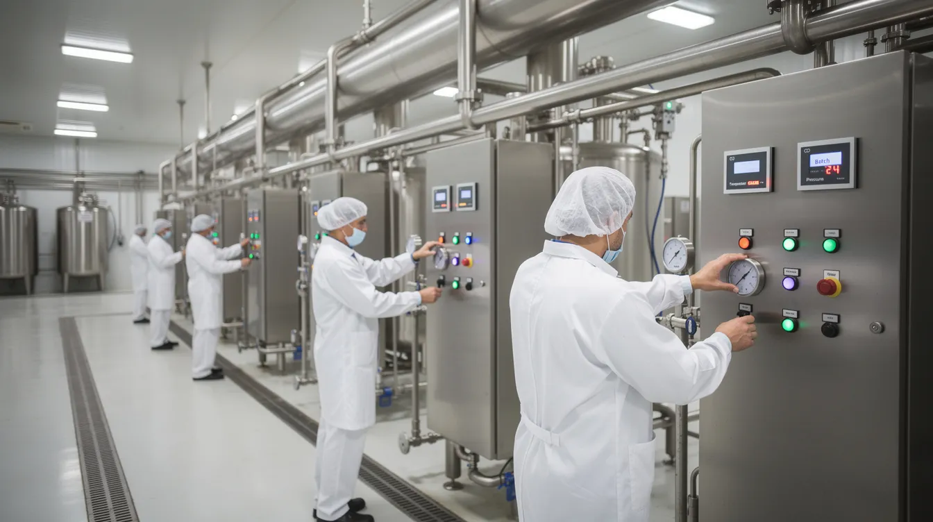
Dairy plant layout must ensure hygienic separation of zones. Hygienic zoning involves dividing the plant into zones according to contamination risk – from external uncontrolled areas through low-hygiene raw zones, medium-hygiene processing areas, high-hygiene filling and packaging zones, to finished-product storage. Zoning hygienic design involves dividing the facility into distinct risk zones based on product exposure. Hygiene zoning separates high-care and low-risk areas, and this separation is fundamental because cross-contamination cannot be corrected by cleaning alone.
Controls between zones include:
- Personnel must change garments when transitioning between zones
- Hand-wash and sanitiser stations at zone transitions
- Footwear changes or foot-baths
- Controlled access and sanitation procedures are crucial for high-care production areas
- Airflow should move from high-cleanliness areas to lower-cleanliness areas
- Positive pressure of greater than 5–15 Pascals is required in high-care zones
The PMO mandates physical separation of raw and pasteurized zones. Pasteurisation and filling require robust protection against contamination risks. Personnel, cleaning and waste flows must be separately designed to avoid cross-contamination. Cleanability should be a primary criterion for the layout of dairy plants. The facility layout must prevent cross-contamination and support smooth plant operations. Cross-contamination risks must be minimised by maintaining physical and operational separation of zones.
Zoning must be tailored to specific products and risk levels, and documented in the plant’s food safety plan as required by FSSAI’s guidance on milk and milk products. FSMA mandates a documented food safety plan for dairy plants, reinforcing the importance of formalised zoning. Avoid placing drains inside high-risk aseptic packaging zones to prevent microbial aerosolisation.
Raw Milk Reception and Storage Area
Layout requirements include tanker entry, weighbridge, sampling booth, milk reception dock and can handling where applicable. Raw milk must be cooled to 45°F within 6 hours post-milking – the PMO requires raw milk cooling to 45°F within 6 hours, and the PMO is continuously revised since its origin in 1924.
Raw milk reception and storage should be physically separated from pasteurisation and packaging areas. Adjacency between reception, raw milk filters, plate chillers and raw milk storage tanks is important, but clear separation from pasteurised and high-hygiene zones must be maintained. Plan for future increase in tanker frequency and possible additional raw milk silos, leaving sufficient slab area and utility connections. Basic QC checks at reception – fat, SNF, temperature, MBRT – should link to the laboratory and data-logging systems.
Ingredient Preparation and Blending Area
This area handles sugar, cocoa, flavours, colours, stabilisers, protein concentrates, vitamins and other functional ingredients. Separate dry stores with pallets and racks, humidity control where required, and clearly demarcated allergen zones for cocoa, nuts or protein powders are essential.
Accurate weighing and dispensing stations, dust control, local exhaust for powder handling and easy-clean surfaces prevent contamination. Controlled transfer of prepared premixes to blending tanks – ideally via closed systems or dedicated transfer pumps – avoids spillage. For plants producing protein and functional dairy beverages, ingredient handling and formulation complexity is significantly higher.
Filling and Packaging Hall in Dairy Beverage Plant Layout
The filling and packaging section is where dairy beverage plant layout decisions have the greatest impact on investment, hygiene and manpower efficiency. Space planning varies significantly by packaging technology – PET and glass bottle lines, cup-fillers, pouch machines and aseptic carton lines each have different footprints. For a detailed comparison, see Dairy Beverage Bottling Plant: PET, Glass & Packaging Systems.
Typical equipment includes rinsers, sterilisation tunnels, fillers, cappers, date coders, labellers, check-weighers, shrink-wrappers, carton erectors and palletisers with intermediate conveyors. Controlled environments with air filtration, positive pressure over corridors and temperature control are required, especially for extended-shelf-life chilled products. Setup for effective micro-testing and quality control is crucial at various points in the process, particularly around the filler. Allow sufficient service space around fillers for changeovers and maintenance without disturbing hygiene controls.
Aseptic Processing and Packaging Layout Considerations
Shelf-stable aseptic dairy beverages require more stringent controls over UHT processing, sterile tanks, sterile air and fully enclosed aseptic filling blocks. Physically segregated high-hygiene areas with controlled personnel entry, gowning rooms and dedicated CIP/SIP systems are necessary.
Higher automation levels, closed product paths, sterile utilities and cleanroom-type building finishes define aseptic facilities. Implications for utilities include higher steam, power and compressed air quality requirements, plus enhanced HVAC and air-filtration infrastructure. For a deeper discussion, see Aseptic Dairy Beverage Processing & Packaging Plant.
Cold Rooms and Refrigerated Storage
Cold rooms are mandatory for chilled flavoured milk, milkshakes and short-shelf-life RTD dairy beverages that must be held between 2–4°C until dispatch. A good facility layout features dedicated cooling and storage zones for long-term product preservation.
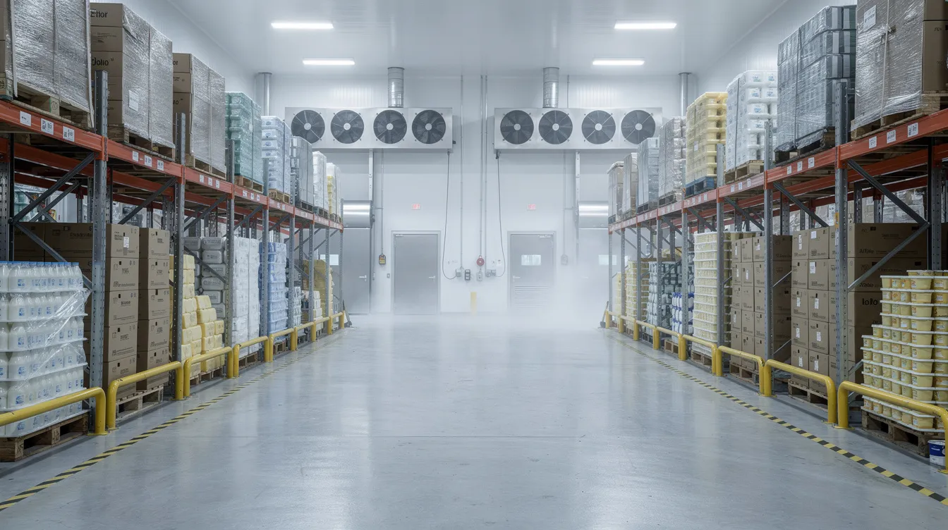
Cold-room capacity is calculated based on daily production, number of inventory days (typically 2–5 days), pallet pattern, stacking height and dispatch schedule. For a 30,000 LPD mixed-product plant, non-frozen cold storage of approximately 70–80 m³ and frozen storage of 25–30 m³ may be required. Design aspects include ante-rooms, air curtains, racking vs floor stacking, forklift corridors and door placement relative to dispatch docks. Aseptic ambient beverages may only need temperature-controlled warehouses, significantly reducing refrigeration load and connected electrical demand.
Raw Material and Packaging Material Storage
Separate storage zones are needed for dry ingredients (sugar, cocoa, stabilisers), flavours and colours (often in cool, dark conditions), and protein or nutraceutical ingredients. Empty packaging – PET preforms, glass bottles, cups, lids, pouches, cartons, shrink films and labels – is bulky and can dominate building area even when the processing plant itself is compact.
Racking vs floor stacking, pest control, humidity control and FIFO for packaging material must be planned. Chemical storage (CIP chemicals, detergents, sanitisers) requires ventilated, bunded rooms away from product-contact raw materials. Inadequate warehouse planning forces frequent purchases, higher logistics cost and inefficient working capital utilisation.
Finished Goods Warehouse and Dispatch
Chilled finished goods warehouses link to cold rooms, while ambient warehouses serve UHT and aseptic dairy beverages – each affects structural and insulation design differently. FIFO and FEFO implementation, pallet racking, staging areas and clear separation from raw material intake routes are essential.
Loading docks with dock levellers, canopy for all-weather loading and adequate truck circulation space support efficient dispatch. Higher dispatch frequency and stable sales patterns may allow lower storage days and smaller warehouses. Finished-goods area size feeds directly into working-capital estimation in the DPR – inventory in days multiplied by daily production and unit cost.
Dairy Beverage Plant Utility Requirements
Utility systems represent a major capital and operating cost head. Utilities typically account for 20–35% of total plant and machinery CAPEX in dairy project estimates. An integrated dairy beverage processing plant layout should place utility corridors and pipe racks logically to minimise line lengths and energy losses. Utilities should be separately routed to reduce cross-contamination and energy loss. Dairy plants require 2 liters of water per liter of milk processed as a baseline, though actual consumption often reaches 3 litres per litre depending on CIP cycles and process configuration.
Electrical Power
Major power consumers include pasteurisers, UHT systems, homogenisers, pumps, refrigeration compressors, air compressors, filling machines, conveyors, cold rooms, lighting and HVAC. Electricity supply for dairy plants typically requires three-phase power. Connected load differs from maximum demand – diversity factors of 0.6–0.8 are typically applied during design. Plan for an internal substation, LT panels, cable routes and possible DG backup, with adequate space for future capacity increase. Accurate power requirement estimates feed directly into the operating-cost section of the project report.
Steam and Thermal Energy
Steam requirements depend on the processes involved in dairy production – product heating, regeneration sections of pasteurisers or UHT units, hot-water generation and CIP cycles. Boilers must be sized after finalising process route, capacity and CIP philosophy, not by thumb rule alone. Insulated steam and condensate lines, steam-trap selection and condensate recovery are key to energy efficiency in steam generation planning. Reliable boiler layout and chimney placement impact both safety compliance and fuel cost.
Refrigeration and Chilled Water
Refrigeration needs cover raw milk chilling, product cooling after pasteurisation, chilled water circulation loops, cold rooms and sometimes air-conditioning of high-care areas. A case study of KMPCL at approximately 40,000 LPD showed cold storage loads of around 56.3 TR and chilling loads of 7.70 TR. Refrigeration systems must be energy-efficient to maintain product safety – refrigeration is often the largest single electricity consumer in a dairy facility. Efficient plant layout shortens glycol and chilled water pipe runs and reduces thermal losses. A dedicated refrigeration plant room with safe access, ventilation and leak-detection is essential, with room for future expansion of compressors and condensers.
Process Water
Main water uses include ingredient water (if used in formulation), CIP and manual cleaning, floor and crate washing, boiler feed, cooling towers, refrigeration condensers and domestic consumption. Water quality – microbiology, hardness, TDS, iron – must be assessed at DPR stage so that the dairy plant water treatment system can be properly designed. Separate lines for potable water, softened water, reverse osmosis water and DM water may be required. Water consumption estimates drive both operating expenses and effluent treatment capacity.
Compressed Air
Compressed air is used for pneumatic valves and actuators, filling and packaging machines, capping and instrumentation. Dairy processing plants need high-purity compressed air to ensure food safety – oil-free or adequately filtered and dried air is required where it contacts product or primary packaging surfaces. Multi-stage filtration and dryers for instrument air, with separate headers for utility air and hygienic air, are advisable. Compressor room location should allow short distribution lines, adequate ventilation and acoustic management.
Water Treatment Infrastructure
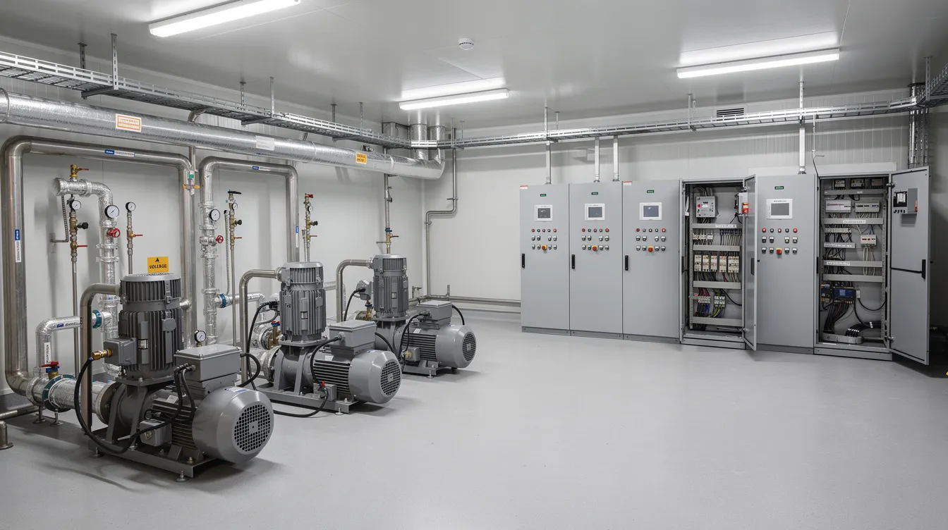
Water treatment configuration depends on raw-water source – borewell, municipal or surface – and its chemical and microbiological profile. Typical units include raw-water storage, pressure sand filter, activated carbon filter, softener, RO plant if required, UV or other disinfection, and treated-water storage tanks. Place the WTP near the raw-water entry point, avoid contamination of treated water and provide safe access for chemical handling and resin regeneration. Under-designed water treatment leads to scaling, product defects and higher chemical consumption, directly affecting operational efficiency and product quality.
CIP System and CIP Room Planning
Clean-in-Place is a critical system for hygienic operation of processing equipment, pipelines, tanks and fillers in a dairy beverage processing plant. Typical CIP components include detergent tanks (caustic and acid), hot-water tank, circulation pumps, heat exchanger, return lines, flow and temperature monitoring and an automation control panel.
Efficient CIP design reduces water usage and downtime during cleaning cycles. CIP utility stations should be positioned strategically to minimise pipe runs and fluid resistance. Integrating CIP and cleaning into the facility design minimises cleaning time and maximises operational efficiency. The CIP room location and manifold layout should minimise dead legs and allow complete coverage of all process circuits. CIP systems have a direct impact on cleaning time, water and chemical consumption, downtime and repeatability of hygiene performance.
Quality-Control Laboratory Requirements
The QC lab handles testing of incoming raw milk (fat, SNF, antibiotics screening), ingredients, in-process samples (standardisation, Brix, viscosity) and finished products (microbiology, shelf life parameters). Basic lab zoning includes a chemical and analytical section, microbiology section (if in-house), sample storage and documentation area, with clear separation from production halls.
Locate the lab close to milk reception and the processing hall, yet physically segregated. Test scope depends on product mix and scale – some advanced tests can be outsourced while core tests remain in-house for timely temperature control and product release. QC capacity and layout influence product-release time and inventory holding, thereby impacting working capital.
Drainage and Floor Design
Dairy plant drainage design is fundamental to hygiene, not a cosmetic issue. Poor slopes or wrong drain locations eventually create contamination and safety problems. Slip-resistant, easily cleanable floors with adequate slope towards hygienically designed drains and trapped gullies are essential. High-strength product-laden effluent (product spillage, CIP discharge) should be segregated from relatively clean cooling water where feasible. Drain covers must be robust, removable for cleaning and placed away from under-equipment zones in high-hygiene processing areas. Floor design must also accommodate thermal movement, trolley and forklift load and long-term maintenance considerations.
Walls, Ceilings, Doors and Internal Finishes
Hygiene-oriented finishes include smooth, washable, non-absorbent wall surfaces with coved junctions between walls and floors. Light-coloured finishes allow easy inspection. Ceilings should minimise dust accumulation and condensation while allowing access to above-ceiling services. Self-closing doors with minimal ledges, insect-proofing and appropriate separation between hygiene zones are necessary. Corrosion-resistant materials are important in wet areas. Well-thought-out finishes reduce cleaning time, pest risk and long-term maintenance cost, directly affecting OPEX and cost control.
Ventilation and Air Management
Ventilation in dairy plants removes heat and moisture from processing halls, controls odours and reduces condensation on ceilings and walls. In high-hygiene and filling areas, filtered supply air, positive pressure relative to adjacent corridors and controlled air changes are required. Boiler rooms, refrigeration plant rooms, compressor rooms and the ETP area need adequate ventilation to manage heat and fumes safely. Air systems must be sized and located in coordination with utilities and building layout to avoid rework.
Personnel Hygiene and Staff Movement
Staff facilities include separate male and female change rooms with lockers, hand-wash and sanitiser points, boot-wash or foot-baths, and appropriate flow to production areas. Toilets should be located away from high-hygiene production areas. Canteen and rest areas must be separated from processing blocks yet readily accessible.
Planned routes for operators, maintenance staff and visitors reduce unnecessary movement through high-hygiene zones. Staff flow and headcount assumptions should be consistent with the automation level and manning pattern used in the DPR’s manpower and salary costing.
Utility Block Planning
Options include a centralised utility block housing boiler, refrigeration, compressors, water treatment, DG sets and electrical panels, or distributed utility rooms attached to each processing block. Design objectives are safe operation, minimal noise and vibration transfer to production halls, easy maintenance access and minimal interference with hygienic traffic. The utility block size must allow for future addition of compressors, boilers or chillers without major structural alterations. Clear separation between fuel storage and food-handling zones is essential, following local regulatory requirements.
Effluent Treatment and Wastewater Management
Main wastewater sources include milk and product spillage, CIP discharge, floor and crate washing, cooling water blowdown and boiler blowdown. Dairy effluent typically carries high organic load and fat, requiring appropriate screening, equalisation, biological treatment and sludge handling. EPA’s effluent guidelines impose stricter standards on new facilities, and California’s CDFA guidelines exceed federal dairy regulations in some respects.
Locate the effluent treatment plant at a lower elevation where gravity flow from drains and sumps is possible, while ensuring odour and aerosol control away from production and office areas. ETP capacity and technology selection must be estimated at DPR stage to size land, civil works and capital cost. Compliance with local Pollution Control Board norms should be verified for the specific state or industrial area.
Internal Roads, Vehicle Movement and Loading Areas
Dedicated movement paths are needed for milk tankers, ingredient trucks, packaging material vehicles, finished-product vehicles and waste or ETP sludge vehicles. Plan entry and exit gates, security cabin, parking bays and turning radii so that vehicles do not reverse into busy pedestrian areas. Segregation of raw milk reception traffic from finished-product dispatch traffic maintains hygiene and reduces congestion. Internal road and hard-paving costs should be captured within land development cost in the DPR.
Fire Safety, Emergency Access and Occupational Safety
Planning requirements include adequate emergency exits, clear escape routes, fire-fighting equipment and hydrant lines, and access for fire tenders around the building. Safety considerations apply around the boiler house, refrigeration plant (especially ammonia systems), chemical stores and electrical rooms. Safe chemical handling areas, eye-wash and showers, and clearly marked safety signage are necessary. Final design must comply with applicable local building byelaws, factory rules, fire department requirements, electrical infrastructure standards and food safety regulations.
Relationship Between Plant Capacity and Infrastructure Requirement
As plant capacity increases, non-linearity appears: utility systems, cold storage and warehouses often need more-than-proportionate upscaling compared to processing areas. Additional raw milk silos, more blending tanks, multiple filling lines, larger CIP systems, bigger cold rooms and expanded dispatch docks become necessary. Higher capacity implies larger connected load, bigger transformers, increased boiler capacity and larger ETP – all of which must be captured in cost estimates. For more on how throughput and product mix drive infrastructure sizing, see Dairy Beverage Plant Capacity Planning & Product Mix.
Relationship Between Machinery Selection and Building Layout
Machinery selection and line configuration should precede finalisation of building columns, foundations and floor levels. Machine dimensions, inlet and outlet heights, maintenance access needs and service connections (steam, chilled water, air, power) dictate structural design and service corridors. Some equipment – tall UHT units or silos – may require higher roofs, special foundations or mezzanines. Realistic machinery footprints and utility loads are also required to prepare an accurate DPR for lenders. See Dairy Beverage Plant Machinery & Equipment Cost for more on equipment-level planning.
Manufacturing Process Flow and Layout Integration
A typical dairy beverage process flow follows: Milk Reception → Standardisation → Ingredient Addition and Blending → Homogenisation → Heat Treatment → Holding and Intermediate Storage → Filling → Packaging → Storage → Dispatch. The building layout must be derived from this process flow and piping and instrumentation diagrams rather than forcing processes into a pre-existing shell building. Each step has specific hygiene, temperature and utility process requirements which influence zoning, pipe routing and floor planning. For readers wanting more depth on liquid milk processing steps, see Dairy Beverage Manufacturing Process & Production Line.
Layout Considerations for Different Dairy Beverage Products
Flavoured milk, chocolate milk, milkshake, protein beverages and multi-product RTD facilities each impose different demands on layout, utilities and storage. Below are the key infrastructure implications for each product type.
Flavoured Milk
Chilled flavoured milk production centres on pasteurisation, homogenisation, short holding and cold-chain requirements from filler to consumer. Ingredient complexity is moderate – sugar, flavours and stabilisers – with need for dedicated blending and filtration to avoid sedimentation. Adequate cold-room capacity and quick dispatch routing are critical. For a complete project overview, see Flavoured Milk Manufacturing Plant Project Report.
Chocolate Milk
Cocoa dispersion, higher viscosity and sediment control through proper mixing and homogenisation add process steps. Dust control and allergen management in cocoa handling areas require suitable separation from non-cocoa dairy products if produced on the same site. See Chocolate Milk Manufacturing Plant Project Report for layout variations including the cocoa preparation room.
Milkshake Manufacturing
Milkshakes are generally higher in viscosity, may include cream, stabilisers and particulates, and require specific blending and filling equipment. Implications extend to pipe sizes, pump selection, filler design and cold-chain robustness from filling hall to market. For product-specific infrastructure details, see Milkshake Manufacturing Plant Project Report.
Protein and Functional Dairy Beverages
Handling protein concentrates, isolates, fibres, vitamins and minerals requires separate powder storage and controlled dispensing rooms. Precise dosing, strong mixing and longer formulation-development trials may warrant a pilot area or R&D corner within the plant. See Protein & Functional Dairy Beverages Manufacturing Plant Project Report.
Multi-Product RTD Dairy Beverage Facilities
Producing multiple products and pack sizes increases SKU count, change-over frequency, intermediate storage and packaging-material variety. Flexible processing and filling lines, additional buffer tanks, clearly separated allergen zones and robust scheduling are necessary. See Ready-to-Drink Dairy Beverages Manufacturing Plant Project Report.
Future Expansion Planning
Designing for current volumes without expansion capacity is a mistake. Future expansion should be included in the original site plan. Leave corridors and open slabs for additional processing tanks, future filling lines, enlarged cold rooms and extra utility equipment. Modular layouts allow scaling without shutting down production – extending the processing hall and warehouse in one direction while reserving transformer, boiler and chiller space for additional units.
Avoid both extremes: over-buying land and overbuilding locks capital unnecessarily, while a site with no expansion flexibility creates expensive constraints later. Lenders often see future expansion capability as a positive, provided present investment remains financially viable. Future proofing through modular thinking is far cheaper than retrofitting.
How Land and Building Decisions Affect Project Cost
Major infrastructure-related capital cost heads include land, land development, factory building, processing halls, cold storage, warehouses, utility buildings, internal roads, drainage, boundary wall, electrical infrastructure, water systems, ETP, laboratory and administrative facilities.
Underestimation of building and infrastructure cost is a common reason DPRs differ from actual project expenditure, affecting term-loan requirement and promoter margin. Choices like compact multi-storey buildings vs horizontal spread influence RCC and steel cost, material-handling equipment and future expansion ease. For detailed cost-category discussion, see Dairy-Based Beverage Manufacturing Plant Setup Cost in India. All cost examples are indicative and must be refined using actual quotations, structural designs and site conditions before financial closure.
Balancing Capital Cost and Hygienic Design
Cost optimisation must not compromise hygiene, maintainability, product safety or process robustness. Common poor cost-cutting examples include cramped processing halls, inadequate drainage, undersized warehouses, no adequate space for utilities or CIP room, and poor personnel segregation. Equally, over-specification risks exist: oversizing cold rooms without sales justification, luxurious office blocks vs under-investment in core utilities, and overdesigned structures with no utilisation.
A balanced approach prioritises capital allocation for food safety, process reliability, energy efficiency and scalable capacity.
Information Required Before Preparing the Layout
Before making final dairy beverage plant layout drawings, promoters should assemble:
- Installed capacity (LPD), operating days and shifts
- Detailed product mix, SKUs and pack sizes
- Packaging formats and technologies
- Machinery list with capacities and GA drawings from vendors
- Anticipated storage days for raw milk and finished products
- Dispatch frequency and distribution radius
- Level of automation and manpower plan
- Tentative utility loads (power, steam, refrigeration, water, compressed air)
- Lab testing scope
- Plot size and shape, road access, FSI and building-height rules, set-back and environmental stipulations
This information underpins both the physical layout and the financial modelling of production, sales, working capital and debt-service ability in the DPR.
Role of Plant Layout in a Bankable Dairy Beverage DPR
A realistic dairy beverage plant layout links capacity, machinery, building area, utilities, manpower, production targets and working-capital cycles into consistent financial projections. The chain runs as:
Capacity → Machinery → Building & Utilities → Production Plan → Sales Volume → Raw Material & Packaging Procurement → Inventory Levels → Working Capital → Profitability → Debt Servicing
Inconsistent assumptions – inadequate cold storage paired with long shelf life targets, or low utility sizing for large capacity – are easily spotted by experienced lenders and can delay sanctions. Realistic utility and building assumptions reduce variance between projected and actual costs, strengthening project credibility with banks.
Common Dairy Beverage Plant Layout Mistakes
- Freezing building design before machinery layout is finalised
- Ignoring future expansion corridors and utility space
- Inadequate cold-room capacity relative to product mix and dispatch frequency
- Narrow product flow corridors creating congestion and contamination risk
- Raw milk and finished-goods traffic using the same congested gate
- ETP or boiler placed far from effluent or steam users, increasing pipe runs
- Poor drainage leading to standing water in processing areas
- Difficult maintenance access with equipment jammed against walls
- Under-sized packaging-material stores forcing frequent, inefficient procurement
- No dedicated chemical or CIP room
- Overlooking personnel hygiene facilities and staff movement design
Involve experienced dairy technology and finance consultants early to review conceptual layouts and prevent such issues from becoming embedded in the project.
Practical Perspective from CA Manish Gugliya
When I prepare a DPR for a dairy beverage manufacturing project, I do not look at land, machinery and financial projections as isolated components. A realistic project requires every technical assumption to reconcile with capacity, production days, product mix, machinery, civil construction, utilities, manpower, inventory, sales, working capital, profitability and loan repayment.
I cross-check whether proposed capacity, infrastructure and utilities are consistent with targeted sales volumes, working-capital funding and expected DSCR. If a promoter plans 50,000 LPD of chilled flavoured milk but has budgeted cold-room capacity for only 20,000 litres of finished goods with five-day dispatch cycles, the numbers will not hold up – either in plant operations or in the banker’s appraisal.
Early coordination among equipment suppliers, architects, structural engineers, utility designers and the DPR and finance consultant can reduce costly rework later. This is an integral part of how I structure project reports, CMA data, financial projections and feasibility analyses – ensuring that design decisions on the factory floor translate into credible numbers in the boardroom.
Frequently Asked Questions
How much land is typically required for a medium-scale dairy beverage plant in India?
Land requirement depends on capacity, product mix, warehouse and ETP size, internal-road design, local FSI and Goma Engineering or other vendor-specific equipment footprints. No single figure applies universally. A 1,00,000 LPD plant may need approximately 1.0–1.5 acres, but a 20,000 LPD plant with a simpler product mix could operate on 0.3–0.6 acres. Promoters should develop capacity, layout and zoning inputs with technical consultants to arrive at a realistic plot-size range before land purchase.
Is a cold room compulsory for every dairy beverage processing plant?
Cold rooms are essential for chilled products like flavoured milk and milkshakes. Ambient UHT or aseptic beverages may use non-refrigerated warehouses, though temperature-controlled environments may still be needed in hot climates. The decision should be based on product shelf life, distribution pattern and market distance. Cold-storage cost and power load must be accurately reflected in the DPR.
Can one plant manufacture flavoured milk, milkshake and protein beverages together?
A multi-product RTD dairy beverage plant is feasible but requires careful design of ingredient handling, allergen control, CIP systems, buffer tanks and flexible filling lines. Such plants need more complex layouts and scheduling, which should be modelled in capacity and financial planning. Regulatory standards for allergen management and hygienic zoning become more demanding in multi-product manufacturing scenarios.
At what stage should I finalise the dairy beverage plant layout?
A conceptual layout should be prepared alongside capacity planning, process selection and preliminary machinery configuration – not after civil works have started. The detailed layout should be frozen only after receiving vendor GA drawings, utility loads and site or FSI constraints, and then used to refine the DPR and cost estimates. Getting the design right at this stage prevents expensive redesign during construction.
Are land and building costs normally included in a dairy beverage plant DPR?
A comprehensive dairy beverage plant project report should include land purchase or lease cost, land development, buildings, utilities, ETP, roads and all related infrastructure as part of project cost. Excluding or underestimating these heads leads to funding gaps, cost overruns and difficulties during bank appraisal. These costs are an integral part of the means-of-finance structure and directly affect promoter contribution and term-loan sizing.