Key Takeaways
- UHT milk plant land, building and hygienic layout requirements must be planned together with process flow, aseptic design and future expansion – not treated as a stand-alone civil construction exercise.
- No single land or building figure suits all UHT plants. Actual area depends on capacity (LPD, KLPD, LLPD), processing technology, product mix, packaging format, utility installations and regulatory setbacks.
- A hygienic UHT milk plant layout must enforce one-way movement of milk, people, packaging materials and waste, with strict separation of raw, processing, high-hygiene and aseptic filling zones through physical barriers.
- Mistakes in plant layout – drainage, zoning, tanker access, warehouse size, ETP location – are expensive to rectify and directly affect project cost, DPR assumptions and bank finance viability.
- Promoters should link technical layout drawings with realistic financial projections and bank-loan documentation. CA Manish Gugliya at ProjectReportBank.com advises integrating technical, regulatory and financial expertise from the earliest planning stage.
Introduction: Land, Building and Hygienic Layout in a UHT Milk Plant
Planning a UHT milk processing plant layout is fundamentally a food safety and investment decision. It is not merely an architectural drawing exercise. UHT milk – heated to 135–150°C for 2–4 seconds to achieve commercial sterility – demands a closed product path from the ultra high temperature treatment unit through aseptic packaging. The factory layout must support this unbroken chain while also accommodating vehicle circulation, utility routing, maintenance access and future expansion.
Poor land and building planning leads to unnecessary material movement, contamination risks, production bottlenecks, inflated civil construction costs and severe disruption during later expansion. This article, written from the practical perspective of CA Manish Gugliya, a practising Chartered Accountant advising on DPRs, bank finance and industrial dairy projects in India, explains how to approach these decisions for commercial UHT plants ranging from 50,000 LPD to 5 LLPD (1 LLPD = one lakh litres per day). UHT milk shelf life ranges from 3 to 12 months depending on packaging format, so the layout must also support long ambient storage and high-volume dispatch.
Why Land and Layout Planning Is Critical for a UHT Milk Plant
Unlike ordinary pasteurized milk, UHT milk must remain commercially sterile from the UHT outlet to the sealed aseptic pack. UHT treatment requires a closed product path after heat treatment. The dairy processing plant layout directly determines whether this sterility is maintained – or compromised. Designing a hygienic layout for a UHT milk processing plant prevents post-pasteurization contamination, which is the single largest quality risk in UHT milk production.
Layout impacts food safety and product quality through:
- Separation of raw and processed paths – preventing raw milk bacteria from reaching sterile zones
- Controlled access to high-hygiene areas – limiting personnel entry to trained, gowned operators
- Correct drainage slope – floors in high-hygiene zones must slope toward drains to prevent standing water
- Air handling – filtered air and pressure zoning in aseptic areas
- Cleanable construction – smooth, washable surfaces that support rigorous cleaning cycles
Production efficiency depends on straight-line process flow with minimal backtracking. Adequate space for UHT modules, homogenisers, aseptic tanks and packaging machines avoids congestion and idle time. CIP (clean-in-place) systems clean UHT processing equipment without disassembly, but they need properly positioned drain points, chemical storage rooms and clear access to all equipment sides.
Layout choices also influence energy consumption. Compact routing of steam, chilled water and compressed air – combined with sensible placement of the boiler and refrigeration plant – reduces heat loss and operating costs. Separate circulation paths for operators, visitors and maintenance staff protect high-hygiene zones while ensuring overhead space for hoists and removable panels near plate heat exchangers.
Regulatory compliance with FSSAI hygienic practices, state pollution control boards and fire authorities becomes smoother when hygienic zoning is clear and well-documented. Banks assessing the project will examine whether the proposed land and building realistically support the projected milk production volumes, making layout planning integral to DPR credibility and bank appraisal.
Factors Determining UHT Milk Plant Land Requirements
UHT milk plant land requirements vary widely. No single “one acre per X LPD” formula works, because the following drivers shape the total plot:
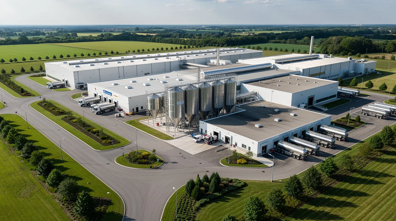
- Installed capacity and reception volume – A 1 LLPD plant needs fewer silos, smaller tanker bays and narrower internal roads than a 3 LLPD facility. For reference, Banas Dairy’s integrated operation processing approximately 5.5 LLPD sits on roughly 122 acres at Palanpur, while Milky Mist’s 3.2 LLPD UHT-plus-other-products facility in Coimbatore has a built-up area of about 2.73 lakh sq ft.
- Production technology – Choosing between direct vs indirect UHT milk processing technology affects hall size and utility block requirements. A direct steam injection system requires flash-cooling modules and more utility space, while an indirect UHT system uses regeneration sections and holding tubes with a different layout footprint.
- Filling lines and packaging formats – Multiple aseptic carton, PET bottle or pouch lines drive hall width, ceiling height and carton warehouse volume. Plastic bottles, aseptic pouches and aseptic carton formats each require different buffer conveyors and packaging-material inventory areas.
- Finished-goods storage – UHT milk can be stored at room temperature for 6–12 months. A storage policy of 90–180 days means a substantial finished-goods warehouse footprint and pallet-racking height.
- Utilities, ETP and safety clearances – Boiler, refrigeration, cooling towers, DG sets, water-treatment plant and ETP each need dedicated land with safety setbacks. The ETP should sit downwind and at a lower elevation.
- Statutory requirements – Internal roads for tankers and 32-ft trucks, fire-safety clearances, greenbelt, statutory open spaces and local setback rules all add to the plot size.
Land selection must be based on a 10–15-year master plan showing potential additional UHT lines, new silos, extended warehouses and utility corridors. For detailed throughput and line-balancing considerations, refer to the guidance on UHT milk plant capacity planning and line balancing.
Illustrative Capacity-Band Comparison (Conceptual – Not a Statutory Prescription)
| Aspect | 0.5–1 LLPD | 1–3 LLPD | 3–5 LLPD |
|---|---|---|---|
| UHT modules | 1 | 1–2 | 2–3 |
| Aseptic filling lines | 1–2 | 2–4 | 4–6+ |
| Silo yard | Small | Medium | Large |
| Finished-goods warehouse | Moderate | Large | Very large / multi-bay |
| Utility block | Compact | Medium | Extensive |
| Expansion provision | Reserve 30–40% plot | Reserve 25–35% | Master-plan driven |
UHT milk processing plants at commercial scale typically require a capacity of 100–200 million litres annually, and these numbers translate directly into substantial land and infrastructure demands.
UHT Milk Plant Site-Selection Considerations
The cheapest plot is not always the most economical. A low-cost site with poor road access, unreliable power or limited water supply can inflate long-term operating costs far beyond any land savings.
Key site-selection factors include:
- Raw milk availability – Dairy plants should ideally be within two hours of milking points. Proximity to milk sources preserves milk quality during transport. Existing collection routes, chilling centres and cooperative networks strengthen supply reliability for both pure milk and formulated dairy products.
- Market access – All-weather road connectivity and reasonable distance to consumption centres reduce distribution cost. Good road access is essential for milk delivery and product dispatch.
- Electricity and water – Availability of 33 kV or 11 kV power, transformer capacity, and a reliable water source (borewell or industrial supply) are non-negotiable. Dairy processing requires large volumes of clean water for production, boiler feed and CIP operations.
- Wastewater disposal – Connection to a common effluent system or provision for an in-house ETP, treated-water reuse and sludge disposal must comply with state pollution-control norms.
- Labour – Proximity to industrial clusters or dairy belts ensures availability of skilled and semi-skilled workers.
- Environmental separation – The site should be distant from heavy-dust roads, chemical factories, tanneries and odour sources. Wind direction and natural drainage should guide positioning of processing, utility and ETP blocks.
- Geotechnical and regulatory – Soil-bearing capacity matters for heavy silos. Flood risk must be assessed. Local zoning laws, land-use conversion requirements and building-height restrictions vary by state and industrial area.
A plot slightly costlier per square metre can deliver lower total project cost through better access, reduced utility expenditure, smoother regulatory approvals and adequate room for future growth.
Capacity-Based Land and Building Area Planning
In practice, land and building estimation starts from the process line layout and expected product mix – not from a thumb-rule area per litre of milk.
The methodology involves:
- Process-equipment footprint – Obtain confirmed general arrangement (GA) drawings from equipment suppliers for UHT units, homogenisers, cream separators, balance tanks, CIP sets, milk silos, aseptic fillers and downstream conveyors.
- Operating and maintenance clearances – Add walking aisles, space for opening heat exchanger frames, lifting pumps, crane access above heavy modules and component-removal corridors.
- Raw-material storage – Size reception bays, silo yards, cream and buffer tank areas and ingredients storage for flavoured milk or other formulated dairy products.
- Packaging-material storage – Estimate based on SKU count, carton or roll dimensions, stacking height, pallet system and monthly inventory policy.
- Finished-goods warehouse – Size based on dispatch frequency, market lead time, desired safety stock and any contract-packed SKUs.
- Utilities and services – Boiler house, refrigeration plant, electrical room, compressor room, water-treatment plant, ETP, engineering workshop – all with safe separation from milk processing zones.
- Laboratories and offices – QC lab near processing, separate microbiology room, and administrative offices.
- External land – Internal roads, tanker parking, car parking, fire-tender corridor, greenbelt and statutory setbacks.
| Functional Area | Basis of Estimation | Major Capacity Driver | Important Planning Consideration |
|---|---|---|---|
| Process hall | Equipment GA drawings + clearances | LLPD, number of UHT lines | Hygiene level, ceiling height |
| Aseptic filling room | Filler dimensions + buffer conveyors | Number of filling lines | Air filtration, restricted access |
| Packaging-material warehouse | SKU count × inventory days × pallet volume | Number of packaging formats | Dry storage, pest control |
| Finished-goods warehouse | Daily output × storage days × pallet footprint | LLPD, dispatch frequency | Ambient temperature, fire safety |
| Utility block | Boiler, refrigeration, compressor, WTP, ETP | Steam and cooling load | Safety setbacks, noise separation |
| Laboratory and offices | Number of QC staff, test volume | Product range complexity | Proximity to process, microbiology isolation |
All numerical illustrations must be validated with equipment suppliers, architects and local authorities before inclusion in the DPR.
Functional Blocks in a UHT Milk Processing Plant
A modern UHT dairy processing plant is divided into distinct functional blocks, each with different hygiene, utility and access requirements. The UHT process includes raw milk reception and cooling as the starting point, progressing through increasingly controlled environments.
Reception and raw-milk handling:
- Security gate, weighbridge and separate entry/exit gates
- Covered tanker unloading bays with CIP stations, sampling platform and quality-testing cabin for adulteration, temperature and acidity checks – located at the “unclean” end of the plant
- Raw milk chilling, fresh milk storage tanks and cold-room positioning adjacent to reception
Processing core:
- Cream separation, milk standardisation and balance tanks connected to UHT units and homogenisers
- Homogenisation and UHT treatment section within the main process hall, segregated from raw-milk areas, with aseptic tanks that maintain sterile conditions before filling UHT milk
- Sterile holding and aseptic filling area with strict hygienic zoning and physical separation from other dairy products handling zones
Downstream and support:
- Secondary packaging: over-wrapping, shrink-wrapping, case packing, date-coding and palletisation flowing forward into the finished-goods warehouse
- Packaging-material warehouse, QC and microbiology laboratory, CIP and chemical-storage rooms, engineering workshop and administrative block
Utilities:
- Boiler and steam generation, refrigeration and chilled-water plant, electrical substation and DG sets, water-treatment plant and ETP – preferably at the periphery, away from high-hygiene zones
Staff facilities:
- Changing rooms, hand-wash and boot-wash stations, toilets, canteen and training room – designed so personnel must pass through hygiene barriers before entering processing or aseptic areas
Hygienic Zoning of the UHT Milk Plant
Hygienic zoning – or dairy plant sanitary zoning – is the backbone of any UHT milk plant hygienic layout. Strict zoning reduces cross-contamination in UHT processing plants by separating areas with different contamination risks using physical barriers.
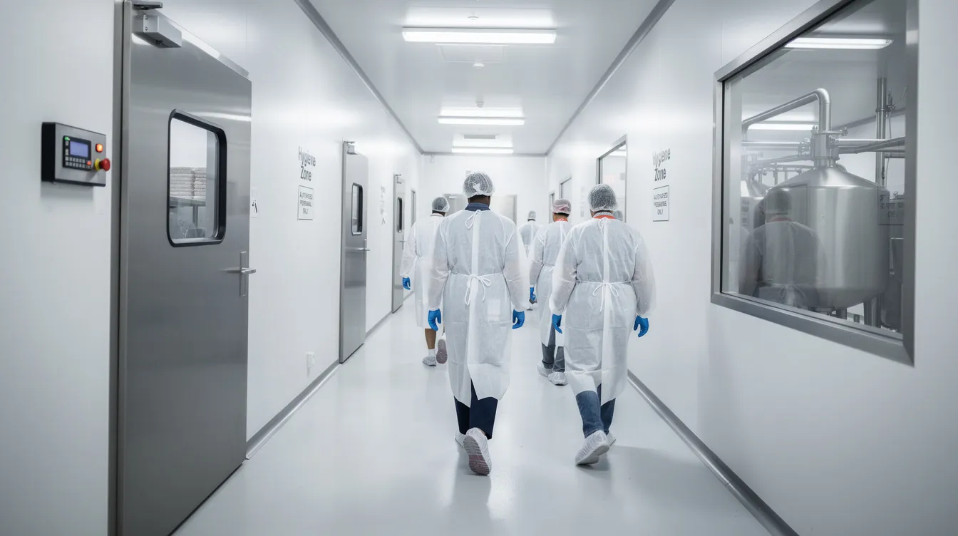
| Zone | Typical Activities | Principal Contamination Risk | Required Controls | Access |
|---|---|---|---|---|
| External / uncontrolled | Roads, truck yards, ETP, fuel storage | Dust, pests, environmental debris | Basic cleanliness, pest control | General |
| Raw milk reception | Tanker unloading, sampling, raw-milk lines | Raw-milk bacteria, soil, external contaminants | Hand-wash stations, boot-wash, separate drainage | Authorised staff |
| General processing | Standardisation, homogenisation, non-aseptic tanks | Medium microbial load, chemical residues | Washable walls and floors, controlled access | Trained operators |
| High-hygiene processing | UHT unit, sterile holding, product milk filter | Post-treatment recontamination | Strict personnel entry, enhanced cleaning, air management | Restricted, gowned staff |
| Aseptic filling | Aseptic fillers, immediate conveyors | Airborne microbes, packaging defects | HEPA-filtered air, positive air pressure, gowning protocol | Authorised and gowned only |
| Packaging / finished goods | Secondary packaging, warehouse, dispatch | Physical damage, pest ingress, traceability loss | Cleanliness, pest control, FIFO | Warehouse staff |
| Utility / waste | Boiler, refrigeration, ETP, scrap | Heat, chemicals, odour, noise | Segregation from product areas, ventilation | Maintenance staff |
The entire UHT dairy processing plant does not operate like a pharmaceutical clean room. Environmental controls must be matched to the product risk and process stage. Designing every area to clean-room standards would be unnecessarily expensive and is not required by current Indian food safety standards for UHT milk processing.
One-Way Product, Personnel and Material Flow
Rooms should progress in a unidirectional flow from raw milk receiving to aseptic filling. The forward-flow principle means raw materials move in one direction through the plant to finished goods, with no crossing or backtracking.
Ideal product flow sequence:
Raw milk reception → chilling and standardisation → UHT processing → sterile holding → aseptic filling → secondary packaging → finished-goods warehouse → dispatch
Separate, clearly marked routes must exist for:
- Raw milk – tankers and pipelines on the “raw side,” never crossing the “finished side”
- Processed UHT milk – sterile piping only, no open handling after heat treatment
- Packaging materials – dedicated doors from the packaging-material warehouse into the packaging hall, avoiding passage through raw-milk or utility areas
- Finished products – forklifts moving from packaging to warehouse and dispatch docks without re-entering processing zones
- Personnel – separate entrances for office and factory staff; change-rooms and hygiene barriers before entering high-hygiene zones; personnel movement should be controlled to prevent cross-contamination between hygiene zones
- Maintenance staff – access corridors or overhead platforms to reach utilities without passing through the cleanest areas
- Cleaning chemicals – secure chemical room connected to CIP, with chemical movement routed away from product and packaging paths
- Waste and rejected materials – waste management should avoid cross-contamination by routing downstream, away from clean areas, through designated collection points and sealed bins
Airlocks, pass-through hatches, restricted-access doors and physical barriers maintain one-way movement and protect the aseptic boundary. For detailed process-sequence understanding, refer to the UHT milk manufacturing process and flow chart.
Building Design and Hygienic Construction Requirements
The dairy processing plant building design must support cleaning, durability and food safety. Materials and specifications can vary, but they must meet FSSAI guidance on establishment design and facilities and good engineering practices.
Floors
Flooring must be waterproof, durable, and easy to clean. Use food-grade, non-absorbent, slip-resistant finishes such as industrial tiles or resin-based systems. Floors in high-hygiene zones must slope toward drains – typically 1–2% gradient. They must resist milk, CIP chemicals and thermal shock, and be free of cracks where harmful microorganisms could harbour.
Walls and Ceilings
Walls in processing areas should be stainless steel or food-grade coated panels for hygiene. Utilize non-porous and chemical-resistant materials for walls and ceilings throughout the processing facility. Surfaces must be smooth, washable and light-coloured, with sealed joints and no ledges. Condensation management and insulation are required in temperature-controlled areas.
Wall–Floor Junctions
Properly coved junctions prevent dirt accumulation and simplify cleaning, especially in processing, UHT and filling areas.
Doors and Windows
Smooth, rust-resistant construction with tight sealing. Self-closing mechanisms where hygiene is critical. Insect-proof screens on necessary openings. Controlled entry to high-hygiene zones via access-control or coded doors.
Drainage
Drainage systems must be designed to prevent standing water in hygienic areas. Correctly sized and trapped drains with easy-to-clean covers. Process-drain networks must be clearly segregated from storm-water drains, and drainage must never flow from low-hygiene toward high-hygiene zones.
Ventilation and Air Management
Ventilation systems control temperature and humidity in dairy plants. Adequate air changes, heat removal from process and boiler areas, local exhaust near hot utilities, and air filtration or pressure zoning in aseptic filling rooms are all necessary to prevent condensation on ceilings and equipment.
Lighting and Pest Control
Adequate lux levels for inspection with shatter-resistant, cleanable fittings. Sealed external openings, paved surroundings, dedicated waste rooms and regular pest-monitoring points form the building-level pest-control strategy.
Layout Requirements for the Aseptic Filling Area
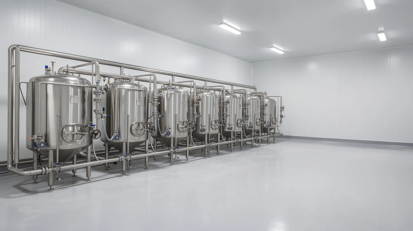
The aseptic filling section is the most sensitive part of the contamination-control layout. Aseptic filling occurs under sterile conditions to prevent contamination, and aseptic packaging prevents recontamination of UHT milk. This zone deserves design attention far stricter than general milk processing areas.
Key requirements:
- Restricted access – only trained, authorised personnel; visitors observe from viewing corridors or windows
- Controlled personnel entry – separate gowning room with lockers, hand-wash, sanitiser, boot-dip, hairnets and masks
- Physical separation – no direct doors from tanker reception or utility zones; entry always through higher-hygiene corridors and airlocks
- Air-quality control – positive air pressure should be maintained in aseptic zones to prevent contamination; filtered air supply; temperature and humidity management to reduce microbial growth
- Sterile product-transfer lines – fully welded or aseptic-coupled pipelines from UHT outlet or aseptic tanks to fillers, with no dead legs. For detailed sterile-boundary concepts, see the article on aseptic filling and packaging process for UHT milk
- Packaging-material handling – controlled entry of pre-sterilised packs, caps and reels; avoidance of dust build-up
- Filler cleaning – dedicated SIP and CIP connections; chemical storage outside but pipeline-connected; floor drains planned to avoid splashing
- Maintenance access – service platforms and external corridors so technicians can work on utilities with minimal opening of the aseptic enclosure
- Monitoring – air sampling, surface swabs, compressed-air filter checks and periodic validation
- Reject handling – segregated bins or conveyors for underfilled or suspect packs, routed out without re-entering clean product paths
Machinery Placement and Maintenance Clearances
UHT milk plant building requirements must be finalised only after the machinery list and preliminary layout are frozen. Constructing the building first and fitting equipment later almost always results in misaligned columns, insufficient ceiling height and problematic pipe routing.
Each major machine – milk reception equipment, cream separator, homogeniser, UHT module, aseptic tank, filler and conveyor – has a defined footprint and maintenance envelope that dictates column spacing and bay widths. Equipment should be spaced adequately to allow cleaning and maintenance access. All product contact surfaces must be accessible to cleaning protocols.
Pipe routing must be straight and short for milk, CIP, steam, condensate and chilled-water lines, with pipe racks that avoid blocking walkways or future expansion. CIP systems must be designed to avoid dead legs and ensure complete drainage throughout the piping network.
Floor loading matters. Heavy milk silos and UHT units may need special foundations; the structural engineer must coordinate with the process designer before finalising building grids. Direct and indirect UHT systems have different layouts for heaters, holding tubes, flash vessels and vacuum systems, so equipment suppliers must provide layout inputs before civil design is frozen.
For the interplay between equipment size, cost and layout planning, refer to the guidance on UHT milk plant machinery and equipment cost.
Utilities and Support Infrastructure
UHT milk plant infrastructure planning must integrate utilities from day one. UHT processes require reliable steam, chilled water, compressed air and power for continuous production runs. Utilities must include water, steam, and electricity for operations across the processing facility.
- Electricity – substation near the plant boundary, cable routing to avoid wet zones, DG sets for emergency backup of critical control systems and UHT units
- Boiler and steam – boiler house with proper chimney clearance, fuel storage (HSD, biomass, gas) away from process blocks, soft-water supply and condensate-return routing
- Refrigeration – ammonia or freon systems, condenser area, cooling towers, insulated chilled-water pipelines to processing rooms
- Compressed air – compressor room with receiver tanks, air dryers and food-grade air distribution to valves, actuators and aseptic fillers
- Water treatment – raw-water storage, filtration, softening, RO (where needed) and treated-water tanks. Punjab dairy plant studies show average water use of approximately 3.31 litres per kilogram of milk processed, with CIP accounting for about 70% of water consumption
- CIP and hot water – central CIP station near the process hall, return-line routing and safe chemical handling with adequate ventilation. CIP systems are essential for cleaning UHT processing equipment effectively
- ETP – located at the lowest site elevation, away from raw-milk and finished-product operations, with separate access for desludging vehicles
- Fire-fighting – underground tanks, pump-house, hydrant ring main and fire-tender access
- Workshop – near utilities for routine maintenance without crossing aseptic areas; organised spare-parts storage
Utilities must remain fully accessible for maintenance but should not create cross-movement through high-hygiene zones.
Packaging-Material and Finished-Goods Warehouse Layout
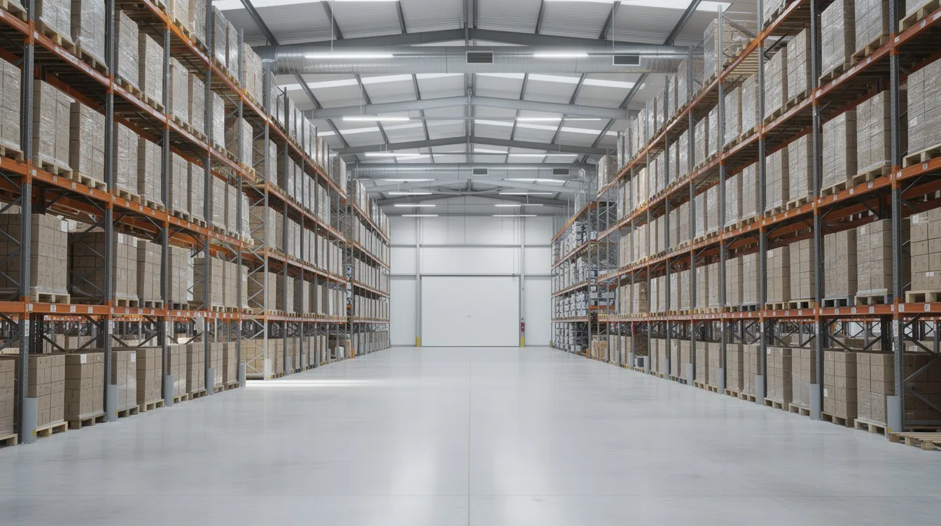
For UHT milk, packaging-material handling and finished-goods warehousing often occupy more land than the core processing block. This is driven by long life dairy products requiring extended ambient storage and high-volume palletised dispatch.
Shelf life by packaging format determines intermediate storage and warehouse sizing:
| Format | Typical Shelf Life |
|---|---|
| Aseptic carton | 6–9 months |
| PE bottle | 6 months |
| Aseptic pouch | 45–60 days |
Packaging-material storage must be dry, clean, elevated on pallets, protected from pests and segregated by SKU. Quarantine zones hold incoming lots awaiting QC clearance. FIFO or FEFO rotation requires clear aisle planning and barcode-based inventory systems.
Finished-goods warehouses must maintain reasonable temperature and humidity even though UHT milk does not require conventional cold storage. Excessive heat or moisture can compromise paper-based aseptic carton integrity and nutritional value. Fire-safety provisions – separation distances, hydrant planning, smoke ventilation – are particularly important in high-stacked areas. For packaging-system-specific warehouse considerations, see aseptic carton packaging systems for UHT milk.
Indian Regulatory and Food-Safety Considerations
UHT milk plant building requirements must align with multiple Indian regulations. Dairy plants must comply with local zoning and environmental laws, and promoters should always verify the latest official notifications.
Key regulatory areas include:
- FSSAI – registration or licence for the dairy plant; compliance with applicable food safety and standards hygiene and sanitary practices for milk and milk products
- Local building approvals – industrial-area layout sanctions, building-plan permissions, height limits, setback rules and occupancy certificates
- Pollution control – consent to establish and consent to operate from the State Pollution Control Board, covering ETP layout, treated-water discharge and sludge handling
- Fire and electrical – fire NOC, emergency-exit layout, compliance with state factory-inspectorate and electrical safety rules
- Voluntary systems – HACCP, ISO 22000 and similar food safety frameworks adopted by many buyers and modern plants for regulatory compliance and export readiness
Requirements vary by state, industrial area, plot size and project capacity. The engineering layout and sanitary zoning should be validated by qualified food technologists, process engineers and architects familiar with dairy technology and sanitary design.
Provision for Future Expansion
Dairy plants should allow for future expansion in their design. UHT milk demand often grows with brand acceptance and rising demand in non-metro and export markets, and most successful plants eventually require additional capacity, new dairy products or new packing formats for sustainable growth.
Master-plan provisions should include:
- Unbuilt bay in the process block for an additional UHT line and aseptic filler
- Extendable silo foundations and spare pipe-rack slots for more raw-milk silos
- Warehouse walls designed for easy removal and rack extension for future growth
- Boiler and refrigeration houses positioned to accommodate additional equipment
- Additional loading docks and dispatch bays for higher throughput
- Reserved floor space and structural strength for automation upgrades (pallet conveyors, automatic case packers) even if installed in a later phase
Utility corridors, underground tanks, roads and storm-water drains must be positioned so they do not block logical expansion areas.
Effect of Land and Building Planning on Project Cost and Bank Finance
Land, site development and civil construction are large components of total investment in a UHT milk processing plant. These costs are crucial in DPRs and CMA data for bank finance.
- Higher land and building costs increase total project cost, promoter contribution and term-loan requirement, and also affect interest during construction and loan-repayment schedules
- An over-designed building inflates fixed assets, weakens DSCR and IRR, and raises depreciation without adding productive capacity
- An under-designed building causes bottlenecks, capacity under-utilisation, unplanned capital expenditure and disruption – reducing operational efficiency
- Accurate layout-based cost estimates support realistic depreciation, fixed-asset coverage and cost-overrun assessment
- Banks typically examine title or lease documents, land-use permission, approved building plans, detailed cost estimates, implementation schedule and infrastructure adequacy
For an overall investment perspective including land, civil work and machinery components, refer to the article on UHT milk processing plant setup cost in India.
Common UHT Milk Plant Layout Mistakes
Rectifying layout mistakes in a running UHT plant is disruptive and expensive. Common errors include:
- Insufficient land – leaving no room for additional silos, fillers or warehouses
- Building before process design – constructing the building before freezing the UHT milk processing plant layout, causing misaligned columns and inadequate ceiling height
- Cross-movement – raw-milk tankers crossing finished-goods loading zones, shared corridors for raw and packed products, or common personnel entry for utility and aseptic-area staff
- Inadequate clearances – insufficient maintenance space around UHT and filling equipment, increasing downtime and service costs
- Poor drainage – flat floors with standing water, drains carrying effluent from low-hygiene to high-hygiene zones, or insufficient slope
- Under-sized warehouses – racks placed in aisles, safety hazards and loss of product traceability
- Utility proximity to processing – boiler, DG and ETP areas too close, causing dust, noise, heat energy waste and environmental impact on product zones
- Inadequate hygiene facilities – missing or poorly designed employee changing rooms and entry routes, flagged repeatedly during food safety audits
- Uniform hygiene treatment – either overspecifying all areas at unnecessary cost or under-protecting the aseptic filling zone
UHT Milk Plant Land and Layout Planning Checklist
Before finalising civil construction drawings or the bank DPR, confirm the following:
- [ ] Capacity finalised in LPD/KLPD/LLPD with confirmed product and packaging mix
- [ ] UHT technology and filler type selected in consultation with process suppliers
- [ ] Process-flow diagram, equipment list, hygienic zoning plan and one-way movement design completed
- [ ] Land-use approvals obtained; site master plan prepared with internal roads, drainage and expansion zones
- [ ] Utilities (boiler, refrigeration, ETP, WTP, DG) positioned with safe separation from processing
- [ ] Warehouses (packaging-material and finished-goods) sized for realistic inventory policy
- [ ] Personnel facilities – changing rooms, hygiene stations, canteen – and QC/microbiology labs planned
- [ ] Fire-fighting plan, emergency exits, electrical safety and structural design validated
- [ ] Environmental clearance and pollution-control consents applied for
- [ ] Civil-cost estimation prepared based on final layout; implementation schedule aligned with machinery delivery
- [ ] All assumptions technically validated before completing the DPR and feasibility report
Professional Perspective of CA Manish Gugliya
In my experience of over 20 years advising on project reports and bank finance for industrial projects, I have consistently observed that the most avoidable cost overruns in UHT milk plants originate from disconnected planning – where the civil architect, process engineer and financial consultant work in silos instead of collaborating.
For every UHT milk plant DPR I prepare, I insist that land and building assumptions are directly linked to confirmed plant capacity, technology choices, machinery quotations, process-flow drawings and utility requirements. An inflated building plan unnecessarily raises capital cost and weakens DSCR. An inadequate one creates bottlenecks and expensive post-commissioning modifications that erode the value chain.
The final engineering layout must be prepared and validated by qualified architects and process engineers. ProjectReportBank.com converts those technical layouts into realistic capital-cost budgets, profitability projections and bank-finance presentations. I always encourage promoters to involve financial, technical and regulatory experts together during planning – rather than treating layout, machinery and finance as separate exercises.
Frequently Asked Questions
How much land is required for a UHT milk plant?
There is no universal acre-per-litre rule. Land needs depend on capacity, technology (direct or indirect UHT), number of filling lines, warehouse volume, utilities, statutory setbacks and planned expansion. Promoters should develop a master plan around the frozen machinery and process layout, then obtain a capacity-specific land estimate from their architect and process supplier rather than relying on generic figures.
How is the building area of a UHT milk plant calculated?
Building area is calculated by summing the footprints of all functional blocks – process hall, aseptic filling room, utilities, warehouses, labs, offices and amenities – with added space for clearances, maintenance and circulation. Engineers typically begin with the detailed equipment arrangement, add percentage allowances for aisles, structural elements and service corridors, and then validate floor loading and heights with structural consultants.
Does an entire UHT milk plant need clean-room conditions?
No. Only certain high-hygiene and aseptic filling zones require enhanced air filtration and environmental controls. Raw milk reception, utility blocks and warehouses follow good hygiene practices but not clean-room standards. Designing every area as a clean room would be unnecessarily expensive and is not required by current Indian food safety standards for UHT milk processing.
How should raw milk and finished UHT milk movement be separated?
The layout should ensure raw-milk tankers, receptacles and pipelines stay on the “raw side” and never cross the “finished side,” where aseptically packed long life milk moves to the warehouse and dispatch area. Separate entrances, clearly segregated corridors and strictly dedicated pipelines ensure that after UHT sterilization and high temperature treatment, milk travels only in sterile, closed lines to aseptic fillers and then in sealed packs.
Does UHT milk require a cold-storage warehouse?
Commercially sterile UHT milk packed in validated aseptic packaging – whether aseptic cartons, PET bottles or pouches – is typically stored at ambient temperature and does not require conventional chilled storage. However, warehouses must still avoid excessive heat and humidity, which can affect packaging integrity and extended shelf life. Some value-added dairy products, such as certain flavoured milk or low fat milk formulations, may have different storage needs depending on composition and market demand.
For assistance with a customised UHT milk plant project report, DPR preparation, financial projections, means of finance, DSCR assessment and bank-loan presentation, contact CA Manish Gugliya through ProjectReportBank.com. Professional guidance does not guarantee loan approval, subsidy eligibility or project profitability – but it strengthens your project’s credibility with lenders and supports well-informed investment decisions.