
Key Takeaways
UHT milk plant utilities form the operational backbone of every ultra high temperature milk processing and aseptic packaging facility. Getting them right determines whether your plant runs efficiently, maintains food safety, meets production targets and generates the financial returns projected in your DPR.
- UHT milk plant utilities-power, steam, water, compressed air and CIP-must be sized based on the actual production schedule, UHT technology type (direct or indirect), filling-line speeds and simultaneous operating loads, not just the rated litres-per-hour capacity printed on equipment brochures.
- Undersized utilities cause production interruptions, incomplete sterilisation or cleaning, food-safety risks and flawed project-feasibility calculations, while oversizing inflates capital expenditure, fixed operating expenses and borrowing requirements without proportional benefit.
- Utility figures are project-specific. Promoters must collect detailed utility-load data from machinery vendors and integrate them into the DPR, steam balance, water balance and financial projections before presenting the proposal to lenders.
- Energy-efficiency measures such as heat recovery, condensate return, variable-frequency drives and optimised CIP cycles materially reduce the UHT milk plant operating cost per litre and strengthen the project’s bankability.
- CA Manish Gugliya focuses on translating technical utility data into realistic Indian-project cost estimates, CMA data and loan-appraisal-friendly documentation, while detailed engineering is carried out by qualified process designers, electrical consultants and equipment vendors.
Introduction to UHT Milk Plant Utilities
Power, steam, water, compressed air and cleaning-in-place systems are the five pillars that keep a UHT milk processing plant running. Every stage of UHT milk production-from raw milk reception and cream separation through homogenisation, sterilisation at 135–150 °C for 2–4 seconds, aseptic storage and aseptic filling-depends on a continuous, high-quality supply of these core utilities. If any one utility falters, the entire sterile chain can break, product quality suffers, and operating costs spiral upward.
UHT processing facilities require utilities that go well beyond what a conventional pasteurisation dairy needs. UHT systems can process milk at capacities ranging from 1 to 50 tons per hour, and large plants can produce 100–200 million litres annually. UHT sterilisation systems use either direct or indirect heating methods, each placing different demands on steam quality, cooling water and electrical supply. The global UHT milk market stood at 130.97 billion litres in 2025 and is projected to reach 205.42 billion litres by 2034, exhibiting a CAGR of 5.10% from 2026 to 2034. Consumer preference for UHT milk, driven by convenience and safety, combined with increasing procurement by urban retail chains, means that Indian promoters setting up new UHT plants must plan utilities with particular rigour.
UHT milk plant utilities cannot be determined from a single number such as “10,000 litres per hour.” They depend on the installed capacity in litres per hour or litres per day, number of operating hours per day, shifts per day, choice of direct vs indirect UHT technology, aseptic tank buffer philosophy, aseptic filling speed, package sizes and formats, CIP regime and simultaneous utility demand. All estimates must be validated with the UHT system supplier, homogeniser vendor, aseptic filling and packaging vendor and utility-equipment suppliers before finalising the detailed project report. This article focuses specifically on utility requirements; for the broader picture of overall investment and project economics, the dedicated article on UHT milk processing plant setup cost in India provides a comprehensive overview.
Why Utility Planning Is Critical for a UHT Milk Plant
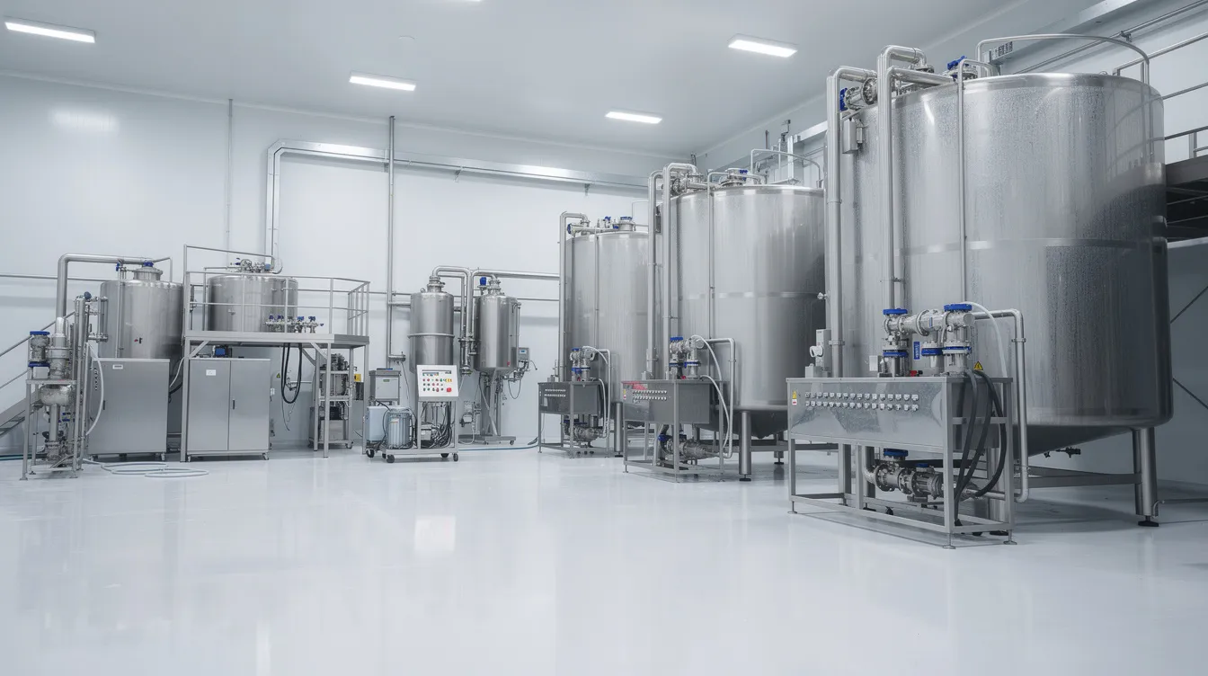
Utilities support every stage in the UHT milk manufacturing process and flow chart. Consider how deeply embedded they are in daily operations:
- Chilled water or glycol for cooling raw milk at reception and for flash cooling sterilised milk after heat treatment
- Electrical power for pumps, a cream separator, homogeniser, filling system and conveyors
- Steam for UHT heat treatment, hot water generation, equipment sterilisation and CIP solution heating
- Treated, high-quality water for process use, CIP rinsing, boiler feed and cooling-tower make-up
- Oil-free compressed air for pneumatic valves, product-diversion systems and aseptic filling machines
- CIP chemicals, heated water and drainage for cleaning cycles across tanks, pipelines and the UHT steriliser
UHT processing equipment includes a raw milk receiving system, and from that very first point through to final packaging, any weakness in UHT dairy plant utilities can halt production mid-shift, compromise commercial sterility or damage sensitive equipment such as plate heat exchangers and aseptic valves. UHT processing achieves a 9-log reduction of thermophilic spores to achieve commercial sterility, which means that even brief steam-pressure drops or cooling-water failures can render an entire batch non-sterile.
Consequences of undersized utilities:
- Frequent tripping of the UHT steriliser due to inadequate steam pressure
- Unstable holding temperature in the sterilisation section
- Incomplete CIP cleaning cycles that compromise food safety
- Inability to run multiple aseptic fillers simultaneously
- Reduced effective production hours and increased product losses
- Higher specific energy cost per litre of milk processed
Consequences of oversized utilities:
- Inflated capital expenditure on transformers, DG sets, boilers, compressors, cooling towers, tanks and piping
- Higher interest cost on project financing
- Fixed operation-and-maintenance charges that persist even at low capacity utilisation
- Poorer return on investment and weaker debt-service coverage ratio (DSCR)
From a bank-finance perspective, incorrect utility assumptions distort electricity, fuel, water and chemical cost projections, ultimately affecting the contribution margin, DSCR and repayment schedule in any DPR or CMA data submission.
Basis and Data Required for Calculating Utility Loads
Before sitting down with equipment vendors or utility engineers, promoters should prepare a structured checklist of inputs. Without these, any utility estimate remains a guess.
Production-related inputs:
- Installed capacity of the UHT plant in litres per hour (LPH)
- Effective daily production volume (LPD), accounting for start-up, shut-down and changeover time
- Number of operating days per year and shifts per day
- Length of production windows versus CIP windows within each shift
- Expected seasonal variations in throughput and product mix
Process-equipment parameters:
- UHT system type (direct steam injection, steam infusion or indirect UHT system using tubular heat exchangers or plate heat exchangers)
- Homogeniser motor rating (kW) and operating pressure
- Cream separator rating and flow
- Aseptic tank volume and number of tanks for intermediate storage
- Filling-line speed (packs per hour by pack size) and number of filling lines
- Product-routing manifold configuration
Utility-specific data to request from each vendor:
- Connected electrical load (kW) with starting current and duty cycle
- Steam consumption (kg/h) at specified pressure (often 7–10 bar gauge)
- Water quality requirements (potable, softened, RO, demineralised)
- Compressed-air pressure, purity class and volume (Nm³/h or cfm)
- Number of CIP circuits and typical cycle duration
Key concepts to understand:
- Connected load is the arithmetic sum of nameplate ratings of all installed motors and heaters.
- Maximum demand is the highest instantaneous electrical load the system must handle, after applying a demand factor.
- Average demand reflects the operating average over an hour or shift, considering duty cycles.
- Diversity factor accounts for the reality that not all equipment runs simultaneously at full load.
- Power factor indicates the ratio of real power to apparent power and affects transformer and cable sizing.
Use a spreadsheet to map simultaneous operations-for example, the UHT unit plus one filler running at full speed while CIP is active on another circuit. This worst-case scenario sets the peak demand that transformers, boilers and compressors must handle. Simply summing all connected loads without applying diversity leads to expensive oversizing.
Future expansion should also be considered. If the plant may grow by 50–70% in throughput over five to seven years, it is prudent to size the main transformer, boiler header and water-treatment capacity with that margin, even if the initial equipment installation is smaller.
Power Requirement for UHT Milk Processing Plant
The UHT milk plant power requirement covers process motors, refrigeration, utility equipment and building services. Electrical power supply supports heavy machinery such as pumps, homogenisers and filling machines, and electricity consumption in a UHT milk plant is one of the largest contributors to operating cost after raw milk.
Major electrical load groups:
- Milk reception and transfer pumps
- Clarification, cream separation and standardisation drives
- High-pressure homogeniser motor (often one of the single largest electrical consumers)
- UHT processing skid (feed pump, booster pump, holding-tube flow control)
- Aseptic tank agitators
- Aseptic filling machines and secondary packaging (cartoning, shrink-wrapping, conveying, palletising)
- Chilled-water plant and cold-room compressors
- Cooling-tower fans and circulation pumps
- Water-treatment plant (RO high-pressure pumps, dosing pumps)
- CIP pumps and heating elements
- Air compressors and dryer motors
- Boiler fans, feed-water pumps, fuel-handling equipment
- Effluent-treatment plant blowers and pumps
- Laboratory, quality-control instruments, lighting, HVAC and office loads
Preparing the electrical load schedule:
For each item, record the nameplate kW, quantity, estimated duty cycle (percentage of time the motor is running), starting method (DOL, star-delta, soft starter, VFD) and whether it operates in parallel with other major loads. A simple hypothetical illustration: if the connected load totals 800 kW but diversity analysis shows that no more than 65% runs simultaneously at any instant, the maximum demand becomes approximately 520 kW. The transformer and DG set would be sized to cover this peak demand plus a 15–20% margin for future growth.
AMUL’s sustainability data illustrate how packaging format alone can swing the UHT processing plant electrical load: aseptic carton packaging consumed roughly 25–27 kWh per 1,000 litres, whereas PET bottle packaging required approximately 115–135 kWh per 1,000 litres. These are real-world published figures, not design standards, but they highlight why the choice of filling system and packaging format must be factored into electrical planning.
Electrical infrastructure:
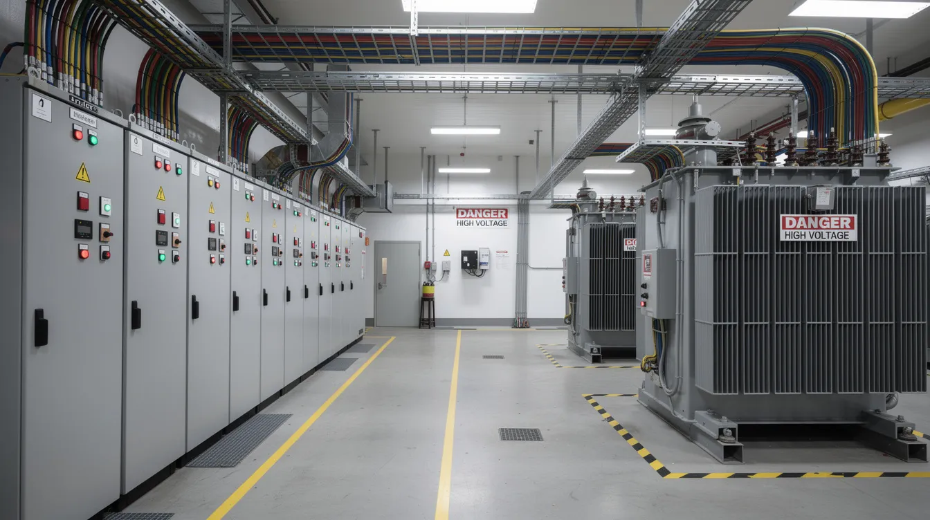
- Transformer rated for peak demand plus expansion margin, with appropriate voltage (typically 11 kV to 415 V in Indian conditions)
- LT panels, motor-control centres, VFDs for variable-torque loads like CIP pumps and cooling-tower fans
- Automatic power-factor correction panel (target power factor above 0.95)
- Heavy-duty generators and UPS systems are necessary to prevent production interruptions, especially for the UHT steriliser PLC, aseptic filler controls and critical valves
- Harmonic filters where multiple VFDs are installed
Voltage dips and sudden outages in Indian grid supply can trip the UHT steriliser, forcing a full re-sterilisation cycle and wasting product, time and energy. UPS backup for control systems is not optional-it is a food-safety requirement.
Energy-saving measures:
- Install IE3 or IE4 high-efficiency motors
- Use VFDs on pumps and fans where flow varies
- Schedule heavy loads outside peak-tariff windows
- Meter electricity consumption area-wise (UHT line, refrigeration, utilities) to monitor kWh per 1,000 litres
- Maintain equipment to prevent efficiency degradation
Detailed equipment-wise power data will form part of the vendor’s technical offer. For a deeper discussion of equipment specifications and costs, refer to the article on UHT milk plant machinery and equipment cost.
Steam Requirement and Boiler Capacity in UHT Milk Plants
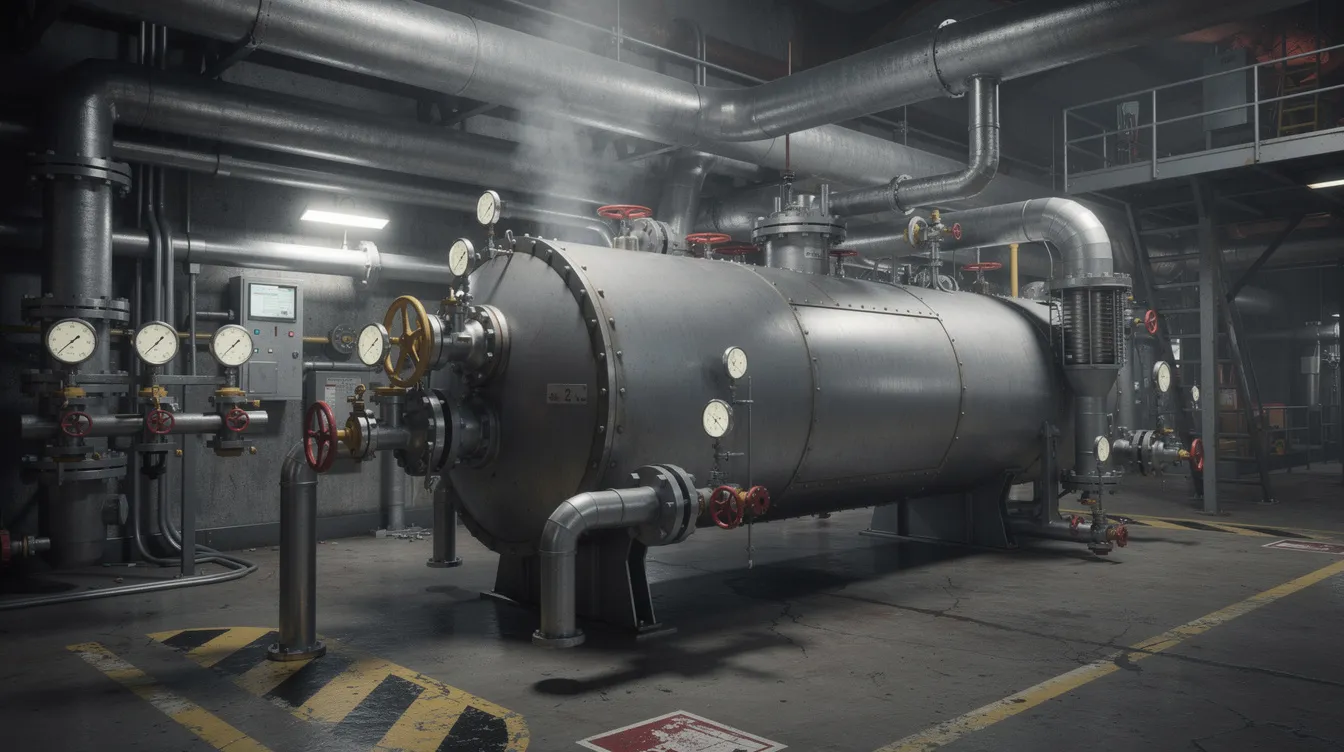
Steam provides the heat energy for the most critical step in UHT milk processing: raising milk temperature to the sterilisation temperature of 135–150 °C within seconds. Beyond the UHT unit itself, steam is consumed for hot water generation, CIP solution heating, sterilisation of process equipment and aseptic tanks, and sometimes for building heating in colder regions.
Types of steam in a UHT plant:
- Plant steam: general-purpose saturated steam from the boiler, used via heat exchangers for indirect heating
- Culinary (food-grade) steam: filtered, low-carryover steam suitable for direct steam injection or infusion, where condensed steam becomes part of the product
- Clean steam: required in some pharmaceutical-grade or specialised aseptic applications
Direct UHT systems inject steam directly into milk for heating, meaning any impurity in the steam ends up in the product. Steam quality in these systems must be exceptionally high. Indirect UHT systems use heat exchangers-plate heat exchangers or tubular heat exchangers-as the heating medium, keeping steam and product separated. The choice between these technologies has significant implications for steam consumption; comparative studies have shown UHT processing energy in the range of 573–667 kJ per kg of milk, significantly higher than conventional pasteurisation. For a detailed comparison, the article on direct vs indirect UHT milk processing technology covers the trade-offs comprehensively.
Where steam is consumed:
- Product heating in the UHT unit (largest single consumer)
- Regeneration section supplementary heating
- Hot water generation for CIP and sanitation
- Pre-sterilisation and SIP (sterilisation-in-place) of the UHT system, aseptic tank and filler product paths
- Steam chamber sterilisation in certain aseptic filling equipment
Sizing the boiler:
Collect the steam flow (kg/h) required by each consumer from vendor data sheets. Apply a simultaneity factor based on the operating schedule-not all consumers peak at the same instant, but CIP and UHT sterilisation often overlap, creating a sharp demand spike. Add distribution losses (typically 10–20% as a design allowance, depending on pipe length and insulation quality) and a standby margin for start-up surges.
A simplified approach:
Required boiler capacity (kg/h) = (Sum of individual steam flows × simultaneity factor) + distribution losses, divided by boiler efficiency (typically 0.80–0.88 for well-maintained fire-tube boilers).
High energy demand is a recognised challenge for UHT processing. Recovering condensate and returning it to the boiler feed-water tank reduces fuel cost, make-up water consumption and boiler-chemical usage. Flash-steam recovery from high-pressure condensate is another measure with attractive payback in Indian dairy plants. Properly functioning steam traps, insulated steam pipelines and correctly set pressure-reducing stations all contribute to steam generation efficiency.
There is no single standard boiler capacity applicable to every UHT plant. The final sizing must be confirmed through a detailed steam balance prepared by boiler and process engineers.
Water Requirement, Quality and Water Balance
Water is a key utility in dairy processing, and high volumes of treated water are necessary for various processes like cleaning and rinsing. In a UHT milk plant, water serves multiple purposes:
- Process water incorporated into the product (e.g., reconstitution of milk powder for formulated dairy products, dilution water)
- CIP pre-rinse, intermediate rinse and final rinse
- Boiler-feed water (softened or demineralised) and blowdown
- Cooling-tower make-up and chilled-water circuit top-up
- Floor washing, crate cleaning, equipment exterior washing
- Aseptic packaging machine cooling and lubrication
- Laboratory analysis and quality-control testing
- Domestic use for staff facilities
Water-quality categories:
- Potable water meeting BIS IS:10500 standards for all product-contact and CIP final-rinse applications
- Softened water for boiler feed to prevent scaling on heating surfaces
- RO or demineralised water where specified by UHT or packaging equipment vendors
- Cooling-tower make-up water, treated to control scaling, corrosion and biological growth
Process water quality for UHT milk must meet stringent microbial and chemical limits. Treatment typically includes pressure sand filtration, activated carbon filtration, water softening, reverse osmosis and UV disinfection, configured based on the raw-water source quality.
Preparing a water balance:
List daily requirements for each application:
- Process water: litres per litre of milk processed (typically a fraction, unless reconstitution is involved)
- CIP cycles: total volume per cycle multiplied by number of cycles per day; pre-rinsing, cleaning and sanitation cycles consume significant amounts of water in UHT plants
- Boiler-feed water: net steam consumption plus blowdown losses
- Cooling-tower make-up: evaporation, drift and blowdown losses
- Domestic consumption: based on staff count and regulatory norms
- Losses: leakages, drainage, unrecoverable wastewater
As a hypothetical illustration, a 100,000 LPD plant might require roughly 2–3 litres of raw water per litre of fresh milk processed when all applications are included, resulting in a raw-water intake of 200,000–300,000 litres per day. This is indicative only-actual figures depend on CIP frequency, boiler type, cooling load and recovery practices.
Storage needs include raw-water tanks sized for at least one day’s requirement, treated-water storage, soft-water tanks and emergency reserves for fire-safety systems. Effluent Treatment Plants are necessary to process wastewater generated in dairy plants, particularly the chemical-laden CIP effluent, before discharge.
Any reuse of recovered water-such as condensate, final rinses or cooling-tower overflow-must comply with food-safety and environmental regulations and must never be routed to product-contact applications unless treated and validated accordingly.
Compressed Air Requirement for UHT Dairy Plants
Compressed air is often called the “fourth utility” in manufacturing, and in a UHT milk plant its role is critical. It operates pneumatic valves and actuators across the process line, drives product-diversion systems, powers the form–fill–seal mechanisms in aseptic carton or bottle filling machines, and supports automation throughout the packaging plant.
Categories of compressed air:
- Plant air: general-purpose air for non-critical applications at 6–8 bar
- Instrument air: dry, filtered air for control systems and pneumatic instruments
- Sterile air: oil-free, filtered through absolute-rated sterile filters for aseptic zones and any application with potential product contact
Compressed air must be oil-free, dry and sterile for UHT applications where it contacts or is proximate to the product or aseptic filling zone. Many UHT projects install separate oil-free compressors for critical circuits and use standard lubricated compressors for general plant air.
Design parameters:
- Operating pressure: typically 6–8 bar at point of use
- Free-air delivery (FAD): sum of all consumer air flows (Nm³/h), multiplied by a simultaneity factor and a leak allowance (commonly 10–15% in well-maintained systems, higher in older plants)
- Air receiver: sized to buffer demand fluctuations and reduce compressor cycling
- Dryer: refrigerant type for plant air, desiccant type where lower dew points are needed
- Filtration: particulate, coalescing and sterile filters in sequence for critical circuits
Data from a large Indian UHT facility (Schreiber Dynamix) showed compressed-air consumption of over 211,000 cubic feet per day for the UHT line alone, illustrating the scale of demand at high production volumes.
A simplified compressor-sizing formula:
Required compressor FAD (Nm³/h) = (Sum of consumer flows × simultaneity factor) × (1 + leak allowance) × (1 + future-expansion margin)
Always provide at least one standby compressor for critical aseptic circuits. An air-supply failure to the aseptic filler forces a production stop and potentially a re-sterilisation cycle.
Efficiency tips:
- Maintain correct pressure setpoints-every 1 bar of unnecessary pressure adds roughly 6–7% to compressor energy consumption
- Conduct regular leak surveys; even small leaks add up significantly over a shift
- Clean and replace filters on schedule
- Avoid using compressed air for open blowing where it is not hygienically justified
CIP System Requirements for a UHT Milk Plant
CIP (Cleaning-in-Place) systems are crucial for maintaining hygiene and sanitation in UHT facilities. CIP allows fully or semi-automatic cleaning of tanks, pipelines and process equipment without dismantling, which is essential in UHT aseptic processing where manual cleaning of sealed sterile circuits is impractical.
Equipment typically covered by CIP:
- Raw milk reception silos and balance tanks
- Clarifier and cream separator circuits
- Standardisation and product-routing lines
- Homogeniser product path
- UHT steriliser including the plate heat exchanger or tubular heat exchangers, holding tubes and regeneration sections
- Aseptic tank internals
- Product manifolds
- Filling-machine product circuits (where designed for CIP)
Key phases of a typical CIP cycle:
- Product recovery or preliminary drain
- Pre-rinse with water to remove residual milk solids
- Alkaline (caustic) cleaning at elevated temperature (often 75–85 °C, per vendor recommendation)
- Intermediate rinse
- Acid cleaning where required (to remove mineral deposits from heating surfaces)
- Final rinse with potable water
- Sanitisation or sterilisation before returning to production
Exact temperature, chemical concentration and contact time must follow equipment-manufacturer recommendations and the plant’s validated food-safety procedures. The CIP process in UHT milk processing is not a one-size-fits-all recipe.
CIP’s impact on utilities:
CIP affects multiple utilities simultaneously: steam and hot water for heating solutions, electrical power for CIP pumps and control systems, large volumes of process-quality water, cleaning chemicals and effluent load. When preparing steam and water balances, the CIP demand must be specifically quantified-not treated as a minor add-on.
Configuration options:
- Centralised multi-tank CIP station feeding several circuits through a piping manifold
- Decentralised skid-based CIP for high-risk or remote equipment such as aseptic fillers
- Number of independent circuits depends on plant layout, product mix and the acceptable cleaning-cycle duration without halting production
Monitoring parameters:
- Cleaning time, temperature and chemical concentration at each stage
- Flow velocity to ensure turbulent flow in pipelines
- Return-solution conductivity to confirm rinsing is complete
- Final-rinse water quality
- Periodic microbiological verification before releasing equipment for production
Utilities must be integrated with accurate monitoring to maintain consistent processing conditions during CIP and to generate audit-ready records for food-safety compliance.
Chemical-storage safety requires proper bunding, clear labelling of acids and alkalis, separation of incompatible chemicals, interlocks to prevent accidental mixing, appropriate PPE for operators and safe routing of CIP waste to the effluent-treatment system.
Interaction of Process Technology with Utility Demand
The choice between direct and indirect UHT technology is one of the most consequential decisions for utility demand. Direct systems use high-quality culinary steam (direct steam injection or steam infusion through a steam chamber or vacuum chamber arrangement) and require intense cooling-often through flash cooling under vacuum-after heating. The vacuum pump and associated cooling systems add to both electrical and cooling water demand. Indirect UHT relies on heat transfer through plates or tubes as the heating medium, with high regeneration efficiency reducing net steam consumption.
Modern indirect UHT systems with heat regeneration exceeding 90% can significantly lower specific energy use per litre. However, they may require longer cleaning cycles to address fouling on heating surfaces, potentially increasing water and chemical use. UHT processing can preserve the nutritional value and sensory quality of milk, though extended high-temperature exposure in fouled heat exchangers can lead to undesirable flavour changes through unwanted chemical reactions-another reason CIP frequency matters.
Product range also influences utility demand. Processing whole milk, toned milk, flavoured milk or formulated dairy products involves different holding times, homogenisation pressures (affecting fat globule reduction and fat separation prevention) and CIP frequency. Higher-solids products foul heat exchangers faster, increasing both energy and cleaning needs.
The filling-line speed, number of aseptic fillers and selected packaging format (aseptic carton, HDPE bottle, PET bottle, pouch) influence electrical load, compressed-air consumption and CIP frequency for packaging equipment. For a detailed discussion, the article on aseptic filling and packaging process for UHT milk covers the process and equipment requirements.
Utility planning must be integrated with UHT milk plant capacity planning and processing line balancing to avoid situations where utility capacity or aseptic tank buffering becomes a production bottleneck. The aseptic tank plays a critical role in intermediate storage: aseptic tanks store sterilised milk before filling to prevent contamination and to decouple the UHT unit from filler speed variations.
Utility Load Summary Table (Concept and Structure)
A well-prepared utility load summary table helps promoters, engineers and lenders see the overall utility picture at a glance. The table below uses hypothetical entries to illustrate the structure; actual values must be derived from vendor data and process design for each specific project.
| Utility | Major Consuming Equipment | Unit | Indicative Average Demand | Indicative Peak Demand | Quality / Pressure | Standby Provision | Main Cost Driver |
|---|---|---|---|---|---|---|---|
| Power | Homogeniser, UHT skid, fillers, refrigeration, compressors | kW | 400–600 | 650–900 | 415 V, 3-phase, PF > 0.95 | DG set for critical loads; UPS for controls | Electricity tariff, capacity utilisation |
| Steam | UHT heater, CIP heating, hot water, SIP | kg/h | 2,000–4,000 | 4,500–6,000 | 7–10 bar g; culinary grade for direct UHT | Standby boiler or adequate margin | Fuel cost, boiler efficiency |
| Water | CIP, boiler feed, cooling, process, domestic | m³/h | 15–30 | 35–50 | Potable for product/CIP; soft for boiler | Raw-water storage ≥ 1 day | Water tariff, treatment cost |
| Compressed Air | Pneumatic valves, fillers, automation | Nm³/h | 150–300 | 350–500 | 6–7 bar; oil-free for aseptic zones | Standby compressor | Electricity for compressor |
| CIP (Chemicals + Heating) | UHT unit, tanks, fillers, pipelines | Circuits | 3–6 circuits | Multiple circuits simultaneous | Per vendor recipe | Adequate chemical inventory | Chemical cost, water, steam |
All figures above are hypothetical illustrations for a mid-sized UHT plant and must not be treated as universal benchmarks.
This type of table is typically annexed to the detailed project report and supports technical due diligence by banks and investors.
Methodology for Calculating UHT Milk Plant Utility Consumption
A systematic, step-by-step approach ensures that no major utility demand is overlooked:
- Define the production program: Finalise product mix (whole milk, toned, flavoured milk, long life dairy products), daily volumes, operating days per year and shift patterns.
- Prepare the machinery and equipment list: Include every motor, heater and pneumatic consumer, with nameplate ratings.
- Collect vendor utility data: Obtain kW, kg/h steam, Nm³/h air and m³/h water for each machine under specified operating conditions.
- Calculate average and peak hourly demand: Map which equipment operates simultaneously during production, during CIP and during start-up.
- Identify simultaneous operating loads: Mark the worst-case scenario (e.g., UHT running + two fillers + CIP on a third circuit + refrigeration at full load).
- Add distribution losses and design margin: Typically 10–20% for steam, 5–10% for power (cable losses), 10–15% for compressed-air leaks.
- Assess CIP and sterilisation demand separately: These are often intermittent but peak-intensive.
- Check future capacity-expansion requirements: Size main infrastructure (transformer, headers, water treatment) for planned growth.
- Select standby or redundant equipment: At least for boiler, compressor and DG set serving critical aseptic operations.
- Prepare daily, monthly and annual consumption estimates.
Useful formulas (illustrative):
- Annual electricity consumption (kWh) = Average demand (kW) × daily operating hours × operating days per year
- Daily water requirement (m³/day) = Sum of process, CIP, boiler, cooling and domestic volumes from the water balance
- Peak steam demand (kg/h) = Sum of simultaneous process steam flows × (1 + distribution loss allowance) ÷ boiler efficiency
- Compressor FAD required (Nm³/h) = Sum of consumer flows × simultaneity factor × (1 + leak + expansion margin)
- Utility cost per litre of UHT milk (₹/litre) = Total annual utility cost ÷ Total annual saleable litres
Replace all sample values with plant-specific vendor data and validated engineering calculations before using these formulas in a DPR or financial model.
Capital Cost of Utility Infrastructure
In UHT projects, utilities-power systems, boiler, water treatment, refrigeration, air compressors, CIP and effluent treatment-together form a significant part of total capital expenditure beyond core process and packaging machinery. UHT milk processing plant setup costs include machinery and utilities, and underestimating the utility-side CapEx is a common source of project-cost overruns.
Key cost components:
- HT/LT electrical panels and transformer
- DG set and UPS system
- Boiler with fuel-handling system, chimney and emission-control equipment
- Steam-distribution lines, pressure-reducing stations and condensate-return system
- Raw-water and treated-water storage tanks
- Water-treatment plant including RO, softener and UV
- Cooling tower and chilled-water plant
- Air compressors, dryers, air receivers and filtration
- CIP station with tanks, pumps, chemical-dosing equipment and instrumentation
- Utility piping, insulation and supports
- Instrumentation, SCADA and control systems for utilities
- Effluent-treatment plant
Quotations from utility-equipment suppliers should be evaluated on a total installed-cost basis including freight, unloading, erection, electrical cabling, piping, civil foundations, insulation, commissioning, statutory approvals and applicable taxes. Treating ex-works prices as complete cost is a frequent error.
Utility Operating Cost and Impact on Profitability
Electricity, boiler fuel (furnace oil, biomass briquettes, natural gas), water charges, CIP chemicals, boiler-water chemicals, cooling-tower chemicals, compressed-air energy, maintenance and effluent-treatment charges together form the utility portion of operating costs. While operating costs for UHT plants are typically 70–80% raw milk and raw materials expenses, the utility component significantly influences profitability at the margin. Gross profit margins for UHT milk typically range from 25–35%, so even a ₹0.30–0.50 per litre reduction in utility cost can meaningfully improve the bottom line.
UHT milk does not require refrigeration until opened and can be stored at ambient temperature for 6–12 months, giving it an extended shelf life and a long shelf life advantage. This eliminates cold-chain logistics cost post-packaging-a benefit that partially offsets the higher in-plant energy demand compared to pasteurised fresh milk.
Calculate utility cost per litre at different capacity utilisation levels (e.g., 50%, 70%, 90%). Low utilisation increases cost per litre because fixed standing charges-transformer demand charges, boiler minimum firing rates, compressor idling power-persist regardless of how many litres are produced.
An energy audit of a Rajasthan dairy plant revealed that targeted efficiency improvements in compressed air, chiller operation and condensate recovery yielded annual savings of approximately ₹191 lakh. Payback periods for measures like VFD installation and condensate-return systems were often under 12 months.
Practical levers to reduce utility cost:
- High heat regeneration in the UHT unit (reducing net steam per litre)
- Condensate recovery system returning hot condensate to the boiler feed tank
- Variable-frequency drives on pumps and fans
- Optimised refrigeration setpoints and regular condenser cleaning
- Water recovery from final CIP rinses and condensate (for non-product-contact use, within regulatory limits)
- Optimised CIP frequency and chemical recipes to reduce water, steam and chemical usage
- Preventive maintenance to reduce leaks, fouling and efficiency degradation
Realistic utility cost assumptions must be built into financial projections and CMA data used by banks. Optimistic low numbers can cause cash-flow stress once actual operations begin.
Utility Planning in DPRs and Bank-Loan Assessments
A bankable DPR for a UHT milk plant in India should contain a transparent, equipment-wise view of utility requirements-not just a summary line such as “power: 500 kW, boiler: 2 TPH.”
Typical utility annexures in a well-prepared DPR:
- Machinery-wise connected-load statement with demand factors
- Single-line electrical diagram showing transformer, panels, DG, UPS and major feeders
- Steam balance sheet showing generation, distribution and consumption by process area
- Water balance showing intake, treatment, consumption, recovery and effluent
- Compressed-air load summary with compressor selection rationale
- CIP configuration note with circuit details and cycle parameters
- Installed versus standby capacity for each utility
- Key vendor quotations and technical specifications
These annexures feed directly into sections on capital cost, working-capital estimates (fuel, electricity, chemicals inventory), unit production cost and projected profitability. Incorrect utility assumptions can materially change DSCR and project IRR, leading to either project-finance rejection or post-sanction financial stress.
A Chartered Accountant may prepare or assist with financial projections, CMA data and bank documentation based on technical inputs supplied by process engineers and equipment vendors. No consultant or CA can guarantee loan sanction or future commercial performance.
Common Utility-Planning Mistakes in UHT Dairy Projects
Experienced practitioners and energy auditors regularly observe the following mistakes in Indian UHT project proposals:
- Sizing transformer and boiler only on average demand, ignoring peak loads during simultaneous UHT, CIP and filling operations
- Ignoring CIP and sterilisation steam and water demand entirely, treating them as negligible
- Assuming all machines run at either 100% or 0% without a realistic diversity assessment
- Neglecting the aseptic filling machine’s air, power and sterile-air requirements
- Not accounting for start-up and pre-sterilisation loads, which can exceed normal running loads
- Absence of proper water-treatment and storage provisions, leading to poor boiler water quality and scaling
- Underestimating effluent load from CIP chemical washdowns
- Failing to provide a standby air compressor or boiler for critical aseptic operations
- Oversizing every utility “just to be safe” without a cost–benefit assessment, unnecessarily inflating CapEx and fixed OpEx
- Relying solely on generic online thumb rules or outdated dairy processing handbook figures instead of current vendor data
- Failing to plan for future expansion or to reserve space and routing for larger utilities, making later capacity enhancement expensive and disruptive
Practical Utility-Planning Checklist for Promoters
This checklist is designed for entrepreneurs and project promoters to carry into meetings with process-equipment vendors, utility suppliers, architects, dairy technologists and lenders.
Power:
- [ ] Connected load statement (kW) from each vendor
- [ ] Transformer capacity with demand and diversity factors applied
- [ ] DG set sized for critical loads (UHT, fillers, refrigeration, controls)
- [ ] UPS for PLC, instruments, aseptic-filler controls
- [ ] Power-factor correction and harmonic-filter provision
- [ ] Electrical supply reliability assessment and grid-connection status
Steam:
- [ ] Steam balance based on vendor consumption data
- [ ] Boiler capacity (kg/h) including peak, losses and standby
- [ ] Fuel type confirmed (gas, FO, briquettes, coal) and fuel-storage plan
- [ ] Condensate-recovery system included
- [ ] Steam-distribution insulation and trap specification
Water:
- [ ] Raw-water source confirmed, tested and quantity assured
- [ ] Water-treatment system specified (filtration, softening, RO, UV)
- [ ] Water balance prepared (process, CIP, boiler, cooling, domestic, effluent)
- [ ] Storage tanks sized for at least one day’s requirement
- [ ] Effluent-treatment plant capacity aligned with CIP and process wastewater generation
Compressed Air:
- [ ] Plant air, instrument air and sterile air requirements separated
- [ ] Oil-free compressed air for dairy plant aseptic zones confirmed
- [ ] Compressor FAD, dryer type and filtration stages specified
- [ ] Standby compressor for critical circuits
- [ ] Leak-detection and monitoring plan
CIP:
- [ ] Number of CIP circuits defined with process engineer
- [ ] Cycle time, temperature and chemical type documented
- [ ] Central vs decentralised CIP configuration decided
- [ ] Chemical storage, dosing and safety provisions
- [ ] CIP effluent routing to ETP confirmed
General:
- [ ] Space reserved in plant layout for utility rooms, routing and maintenance access
- [ ] Integration with hygienic zoning and drainage confirmed
- [ ] All utility design assumptions documented in the DPR
- [ ] Vendor offers clearly state utility conditions (pressure, temperature, quality) required for performance guarantees
For detailed guidance on space planning and hygienic zoning, refer to the article on UHT milk plant land, building and hygienic layout requirements.
Plant Layout, Utilities and Hygienic Zoning (Brief Utility Angle)
While full plant layout is addressed in a separate article, utility planning must consider hygienic zoning, pipe routing, condensate drainage and maintenance access within the UHT dairy processing plant. The design of UHT plants must ensure strict separation between hygienic and non-hygienic areas, and utility routing plays a direct role in maintaining that separation.
- Utility rooms (boiler house, compressor room, electrical room, water-treatment area) should be segregated from high-care processing zones yet positioned to minimise steam and compressed-air line lengths, reducing pressure drops and heat losses
- Steam and hot-water lines must be properly insulated, with condensate drainage at correct slopes to prevent water hammer and energy waste
- CIP return lines and drain connections should follow hygienic-slope design, preventing pooling of wastewater near processing equipment
- Compressors and boilers should be located away from food-handling zones to avoid contamination from combustion gases, oil mist and noise
Improper layout increases energy losses, raises operating costs and can make future expansion of utilities expensive. Early coordination between the process designer, architect and utility engineers is essential.
Utilities and Aseptic Filling & Packaging Lines
Aseptic filling and packaging systems for UHT milk are intensive consumers of electricity, vacuum, compressed air and sometimes sterile air, and they typically need dedicated CIP and SIP (sterilisation-in-place) utility connections.
Typical utility needs of aseptic fillers:
- Machine electrical power (motor drives, heating elements, sealing systems)
- Vacuum pump for carton forming or bottle handling
- Compressed air for carton erection, sealing, product-diversion valves and automation
- Cooling water for sealing jaw temperature control
- Sterile-air filtration for the aseptic filling zone to maintain a positive-pressure sterile environment
- CIP and SIP media (hot water, steam, chemicals) for cleaning the filler’s product circuit
The choice of packaging format-aseptic carton, HDPE bottle, PET bottle or pouch-affects total utility load and operating cost. For packaging-side decisions and format comparisons, the article on aseptic carton packaging systems for UHT milk provides detailed guidance.
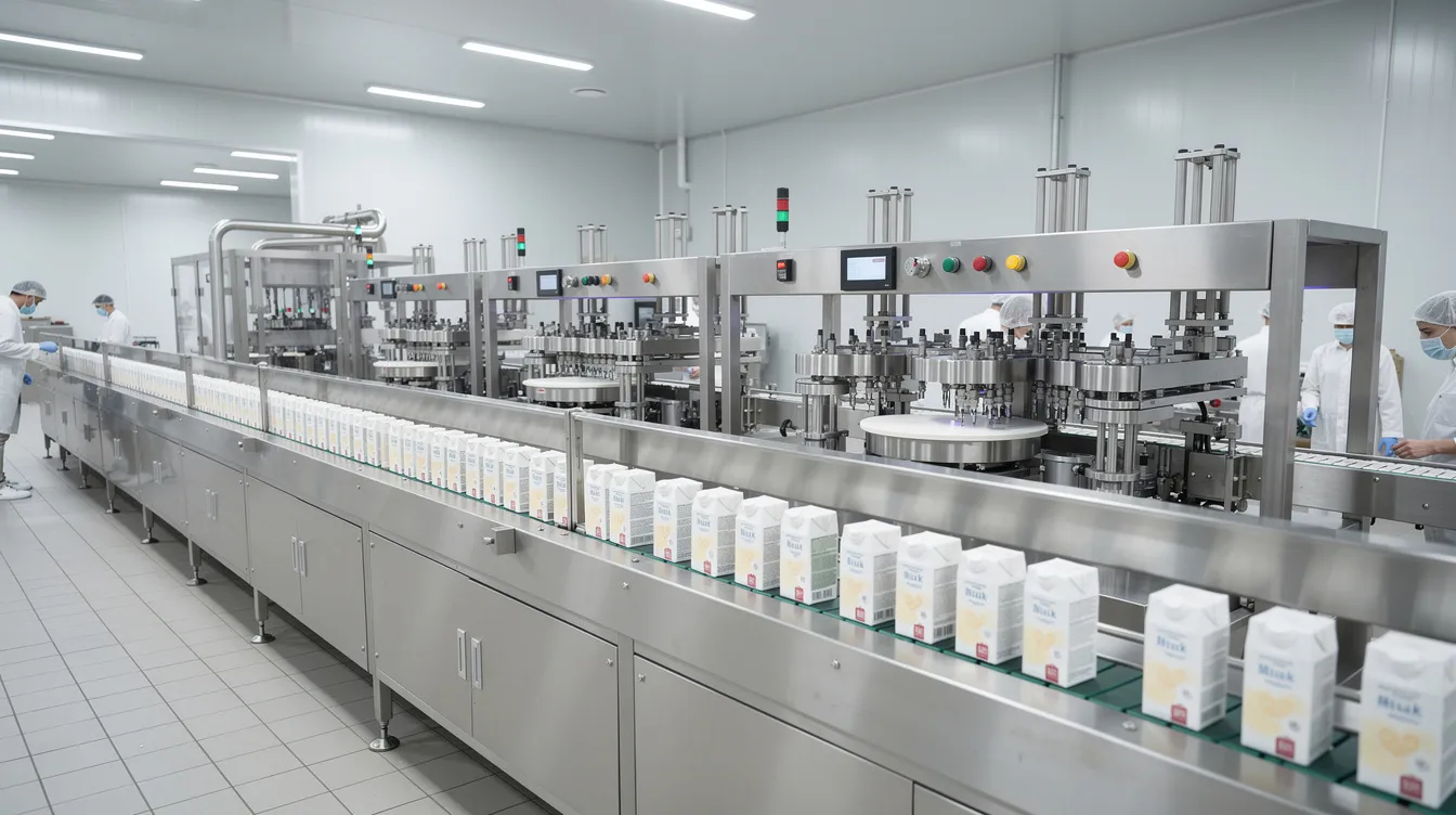
Utility planning should treat the UHT unit, aseptic tank and aseptic fillers as an integrated sterile block. A pressure increase or failure anywhere in the sterile compressed-air supply to the filler can compromise aseptic conditions and force a costly re-sterilisation. UHT milk, which can be stored at room temperature for 6–12 months due to its extended shelf life, relies entirely on the integrity of this sterile chain from steriliser to sealed package to deliver its long life milk promise.
Example: Utility Cost Estimation and Monitoring
The following is a hypothetical illustration for a mid-sized Indian UHT milk plant. All numbers are assumed and must be replaced with actual vendor data and site-specific tariffs.
Assumed parameters:
- Capacity: 200,000 litres per day (LPD)
- Operating schedule: 18 hours production + 4 hours CIP + 2 hours changeover/buffer, 300 days/year
- Packaging: primarily aseptic carton
| Utility | Assumed Consumption | Monthly Quantity (approx.) | Assumed Unit Rate | Monthly Cost (₹ approx.) |
|---|---|---|---|---|
| Electricity | 150 kWh per 1,000 litres | 900,000 kWh | ₹8.50/kWh | ₹76,50,000 |
| Boiler fuel (briquettes) | 0.25 kg steam/litre → ~25 kg fuel/1000 L | 150 tonnes | ₹6,500/tonne | ₹9,75,000 |
| Water | 2.5 litres water/litre milk | 15,000 m³ | ₹25/m³ | ₹3,75,000 |
| Compressed air (power share) | Included in electricity above | – | – | – |
| CIP chemicals | ₹0.15/litre milk | – | – | ₹9,00,000 |
| Effluent treatment | ₹0.05/litre milk | – | – | ₹3,00,000 |
| Total monthly utility cost | ~₹1.02 crore | |||
| Utility cost per litre | ~₹1.70/litre |
This is entirely indicative. Actual costs depend on tariffs, fuel prices, efficiency measures, product mix and capacity utilisation.
Recommended KPIs to track monthly:
- kWh per 1,000 litres of milk processed
- kg steam per 1,000 litres
- m³ water per 1,000 litres
- Compressed-air consumption per 1,000 litres
- CIP chemical cost per 1,000 litres
- Effluent m³ per 1,000 litres
Installing meters and sub-meters at major utility nodes-boiler house, refrigeration plant, UHT line, fillers-helps identify deviations and improvement opportunities. UHT plants that monitor these KPIs from commissioning onward achieve dairy plant energy efficiency improvements much faster than those that rely on aggregate billing data alone.
Frequently Asked Questions
The following FAQs address common promoter queries on UHT milk plant utilities that are not fully covered in the main sections above. Answers are concise and avoid prescribing universal capacity figures.
How early in project planning should UHT milk plant utilities be defined?
Initial utility ranges should be estimated as soon as the product mix, capacity and broad process route are frozen-even before final equipment selection. This allows land procurement, building design and power-connection applications to proceed in parallel. Detailed utility sizing (transformer rating, boiler kg/h, compressor Nm³/h, water-treatment m³/h) must be finalised only after receiving vendor utility data and integrating them into the DPR, steam balance and water balance.
Can I use existing dairy utilities for a new UHT line?
Existing utilities-boiler, compressor, refrigeration, water treatment-may be partly usable if they have genuine spare capacity, appropriate quality (e.g., culinary steam for direct UHT, oil-free air for aseptic filling) and compatible pressures. Conduct a formal load study on the current plant to verify actual maximum demand and available margins, rather than assuming spare capacity from nameplate ratings alone. Adding a UHT line without this study risks overloading existing infrastructure during peak production processes.
Do indirect UHT systems always consume less energy than direct systems?
Modern indirect UHT lines with high heat regeneration typically show lower net steam usage per litre, but overall energy performance depends on design details, product range, CIP regime and heat-recovery arrangements. During flash cooling in direct systems, a vacuum chamber removes the condensed steam added during heating, recovering some latent heat. Promoters should compare vendor offers on specific energy consumption (kWh and kg steam per 1,000 litres) under identical operating assumptions, rather than relying only on generic claims about one technology being universally superior. The choice also affects product quality, since direct systems expose milk to a lower temperature for a shorter contact time on heating surfaces.
How often should utilities for a UHT plant be reviewed after commissioning?
A formal review should be conducted 3–6 months after commissioning, comparing actual consumption against DPR estimates for each utility. After that, annual reviews-or whenever capacity, product mix or operating schedule changes significantly-are advisable. Periodic energy and water audits help identify opportunities for heat recovery in UHT processing, leak reduction and CIP optimisation, particularly as tariffs and environmental norms evolve. UHT milk production efficiency improves continuously when utilities are monitored against defined benchmarks.
Is there any standard benchmark for utility consumption per litre of UHT milk?
Industry studies quote broad ranges-for instance, published AMUL data show electricity consumption varying from roughly 25 kWh to over 130 kWh per 1,000 litres depending on packaging format alone. Benchmarks vary widely with technology, scale, product type (long life dairy products vs flavoured milk), regeneration efficiency and maintenance practices. Promoters should develop plant-specific benchmarks during the first year of operation and then continuously improve them, rather than copying generic global figures without adjustment. The nutritional benefits and extended shelf life of UHT milk justify the higher energy investment, but only when utilities are efficiently planned and managed.
Conclusion and Professional Guidance
Accurate planning of UHT milk plant utilities-power, steam, water, compressed air and CIP-is essential for hygienic processing, aseptic safety, uninterrupted UHT milk production and realistic operating-cost estimation. Each project’s utility requirements are unique and must be derived from detailed process design, vendor utility data and realistic production schedules, then translated into sound financial projections, CMA data and DPRs that withstand lender scrutiny.
Entrepreneurs, investors and consultants planning a UHT milk processing plant in India are welcome to approach CA Manish Gugliya through ProjectReportBank.com for assistance in preparing customised detailed project reports, CMA data, financial projections, working-capital assessments and bank-loan documentation for UHT dairy projects. No guarantee is provided regarding loan sanction, subsidy approval or future profitability-these depend on multiple factors beyond any consultant’s control.
Disclaimer: This article provides general guidance based on typical Indian dairy processing conditions and publicly available industry data. Actual technical design and utility sizing for any UHT milk plant must be carried out and validated by qualified dairy technologists, process engineers, electrical and mechanical consultants and equipment vendors. Preparation of a DPR or financial projection does not constitute a guarantee of project success, loan approval or commercial performance.